
Related Manuals for Deye SUN-30K-SG01HP3-EU


Summarization of Contents
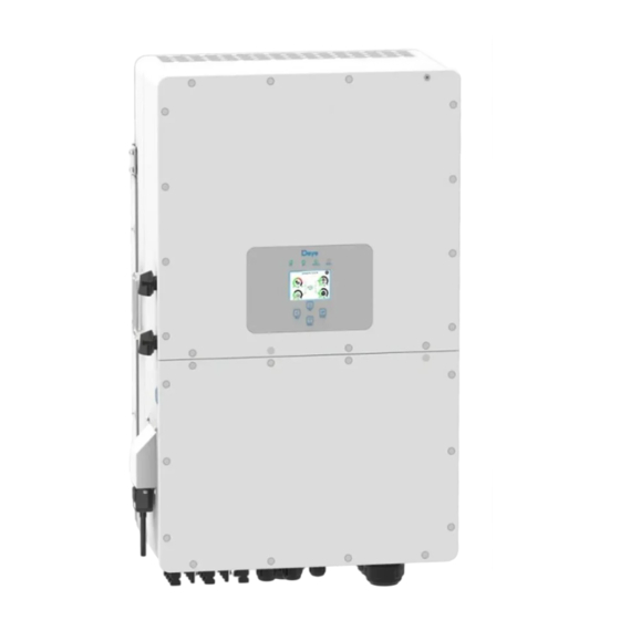
Product Overview
Inverter Component Identification
Identifies key components and ports on the inverter for reference.
Installation Guide
Included Parts List
Lists all components included in the package for installation.
Mounting Instructions
Installation Site Precautions
Precautions for selecting an appropriate installation site for the inverter.
Installation Location Considerations
Factors to consider when choosing the inverter's installation location.
Function Port Definitions
CN1 and CN2 Port Configurations
Defines connections for current transformers, generator start, and other ports.
Communication and Control Ports
Defines ports for meter, parallel, CAN, DRM, BMS, and RS485 communication.
Grid and Backup Load Connection
Backup Load Connection Requirements
Recommended AC breaker size for backup load connection.
Grid Connection Requirements
Recommended AC breaker size for grid connection.
PV Module Connection
PV Module Selection Criteria
Parameters for selecting compatible PV modules based on voltage and certification.
PV Module Wiring Procedures
Steps for connecting PV module wires to the inverter, including polarity.
Operation
Power ON/OFF Procedure
How to turn the inverter on and off using the power button.
Operation and Display Panel Overview
Describes the inverter's operation panel, LEDs, and function keys.
LCD Display Icons
Main Screen Information
Overview of the inverter's main screen, showing system status and energy flow.
Power Curves
Solar Panel Generation Details
Details on solar panel generation, voltage, current, and power.
Backup Load Consumption Details
Details on back-up load power, voltage, and daily/total consumption.
Grid Status and Power Details
Details on grid status, power, frequency, and voltage.
Basic Setup Menu
Factory Reset and Settings Lockout
How to reset inverter parameters to factory defaults and lock settings.
Password Entry for Settings
Password entry screen for accessing factory reset and settings lockout.
Battery Setup Menu
Battery Mode and Capacity Configuration
Configure battery type, capacity, and charge/discharge limits.
Battery Charging and Control Settings
Configure automatic charging and generator control based on battery status.
System Work Mode Setup
Work Mode Configuration Options
Configure inverter operation modes like selling first or zero export.
Zero Export To Load Setting
Setting to power only the connected backup load, reducing grid export.
Zero Export To CT Setting
Power local load and charge battery without selling to grid using CT.
Grid Setup Menu
Grid Code and Level Selection
Select the appropriate grid code standard and set off-grid voltage levels.
Grid Connection Parameters
Configure normal and reconnect parameters for grid connection stability.
Grid Protection Settings
Configure over/under voltage and frequency protection settings for grid interaction.
Generator Port Use Setup
Generator Input and Smart Load Configuration
Settings for generator input and smart load output functionality.
Micro Inverter Input Settings
Configure micro-inverter functionality using the generator port input.
Advanced Function Setup
Solar Arc Fault and Generator Peak Shaving
Configure solar arc fault detection and generator peak shaving for protection.
Communication and Phase Feeding Settings
Configure BMS error stop, signal island mode, and asymmetric phase feeding.
Operating Modes
Basic and Generator Modes
Diagrams illustrating basic and generator operating modes.
Smart-Load and AC Couple Modes
Diagrams illustrating smart-load and AC couple operating modes.
Appendix I: Port Pin Definitions
BMS1 RJ45 Port Pinout
Pin definition for BMS1 RJ45 port.
BMS2 RJ45 Port Pinout
Pin definition for BMS2 RJ45 port.
Meter RJ45 Port Pinout
Pin definition for Meter RJ45 port.
Appendix II: CT Dimensions
Split Core Current Transformer Dimensions
Dimensions of the split core current transformer (CT).
CT Secondary Output Cable Length
Information about the CT's secondary output cable length.
Need help?
Do you have a question about the SUN-30K-SG01HP3-EU and is the answer not in the manual?
Questions and answers