
Related Manuals for Max Machinery P213


Summary of Contents for Max Machinery P213
- Page 1 P-Series User Manual Positive Displacement Piston Flow Meters P001 P002 P213 P214 P215...
- Page 2 For flow meters rated for ATEX, UL, or cUL Class 1, Div. 1 use in a hazardous environment, contact Max Machinery Sales at 707.433.2662 or www.maxmachinery.com. Never run the meter dry or blow compressed air through the meter. Damage will occur.
-
Page 3: Table Of Contents
Troubleshooting and Service Request ...........35 Additional Information Available .............35 Max Machinery, Inc. (MMI) reserves the right to change product specifications without notice to improve performance, reliability, or manufacturability. MMI shall not be held liable for operational, technical, or editorial errors/omissions. Visit our web site for the latest version of this user manual. -
Page 4: How It Works
– from the laboratory to harsh industrial processes. Optional seal materials allow for different fluid compatibility. Max Machinery, Inc. designs, manufactures, calibrates, and refurbishes high accuracy, high resolution, precision liquid flow meters under an ISO 9001:2015 certified quality management system. All Max Precision Flow Meters are tested and calibrated in our lab and provide measurements traceable to NIST. -
Page 5: Installation Mechanical
Fitting kits contain detailed instructions and are shipped with every meter (contact Max Machinery for spare ferrule kits). Always torque to values on fitting kit instructions. Select tubing grades that meet or exceed your system pressure requirements. If using flexible tubing, install a tubing insert to allow compression ferrules to seal (suggested inserts: Swagelok SS-405-2, SS-405-03 or SS- 405-170). - Page 6 Installation - Mechanical Bypass Valves: Install valves to allow system start- up, filter replacement, or flow meter removal without completely shutting the system down and draining the lines. See diagram. Failure to use a bypass at start up may lead to flow meter damage due to debris, overspeeding the meter with air in the lines, and pressure shock due to initial line surges.
-
Page 7: Mechanical Operation
Mechanical - Operation Determine that the following parameters of your flow metering system are within the specifications for the specific meter being used: Maximum System Pressure (Specifications) Differential Pressure across meter (Pressure Drop Curves) Maximum Flow Rate (Pressure Drop Curves) Metered Fluid Temperature (Sales specification, transmitter specifications page 8) If the metered fluid is greater than 28°C (80°F) over ambient, see the “High Temperature Start Up”... -
Page 8: Installation Electrical
Installation - Electrical WARNING: Electrical shock hazard. Serious or fatal injury may occur. Installation/Removal should only be completed by trained and authorized personnel. WARNING: Refer to the EXInstall Sheet for proper installation in hazardous locations. CAUTION: Verify transmitter output type (Analog or Frequency) before wiring. Inappropriate wiring could result in damaging the circuit. -
Page 9: Electrical Quick Start
You must determine if your process automation electronics have the capability to accept the high frequency output of the Max Flow Meter. If your system cannot accept the data at the pre-set frequency, then use the Max Machinery Interface Software Kit to adjust the frequency output to a lower setting that matches your system. - Page 10 Electrical Installation Instructions - 5-pin Turck Connectors Applies only to transmitters with 5-pin, M12 style connectors. For hazardous location transmitters with 1/2 inch conduit connections, please refer to the EXInstall sheet. Frequency Output Transmitters (PN ending N/-) Turck® Connector Mating Cable Pin # Wire Color Label...
- Page 11 Electrical - Operating Information Max Flow Meters require a fully isolated power supply to operate. Refer to the Max Machinery Interface Software Kit Manual for instructions on how to change the flow meter output signal frequency or analog range to meet your application’s equipment needs.
- Page 12 Note: There are no selections or adjustments on the circuit board. Setting changes are made through the Interface Software Kit (SFT-KIT-001), sold separately. If the PCA is not functioning, PCA replacement kits are available by contacting Max Machinery. P-Series User Manual Rev2020A...
-
Page 13: Field Compensation Of Transmitter
An alternating blue/green LED indicates that the circuit is detecting a magnet and provides an output signal. A steady or flashing red LED indicates a problem with the transmitter PCA. Contact Max Machinery to have your flow meter refurbished. - Page 14 The flow meter being compensated must not be used for system flow rate feedback control during this process. The transmitter output is disabled during the compensation routine. If you are unable to run a stable flow in the field, send your meter in to Max Machinery for calibration. The compensation routine is as follows: 1.
-
Page 15: Led Functions
5 revolutions at the stated flow rates. If compensation fails, restart the compensation process. When using the Interface Software Kit, follow instructions provided to correct errors prior to attempting compensation again. If problems persist, contact Max Machinery at 707-433-2662 or at www.maxmachinery.com. -
Page 16: Specifications
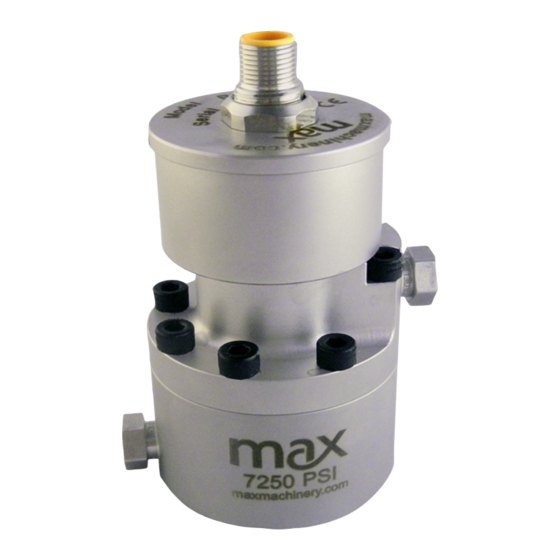
Specifications P001LA SPECIFICATIONS Flow Range 0.005 to 200 cc/min ± 0.2% of reading over a 200:1 range Accuracy (3 cP) Maximum Operating Pressure 250 psi (17 bar) Weight 0.4 kg Recommended Filtration 5 micron Port Size(s) 1/4 inch or 6 mm tube fitting Fluids Most non-aqueous, hydrocarbon based fluids MATERIALS OF CONSTRUCTION... - Page 17 Specifications P001 SPECIFICATIONS Flow Range 0.005 to 200 cc/min ± 0.2% of reading over a 200:1 range Accuracy (3 cP) Maximum Operating Pressure 7250 psi (500 bar) Weight 1.1 kg Recommended Filtration 5 micron Port Size(s) 1/4 inch or 6 mm tube fitting Fluids Most non-aqueous, hydrocarbon based fluids MATERIALS OF CONSTRUCTION...
- Page 18 Specifications P002 SPECIFICATIONS Flow Range 0.5 to 2000 cc/min ± 0.2% of reading over a 200:1 range Accuracy (3 cP) Maximum Operating Pressure 7250 psi (500 bar) Weight 1.9 kg Recommended Filtration 10 micron Port Size(s) #4 SAE Fluids Most non-aqueous, hydrocarbon based fluids MATERIALS OF CONSTRUCTION External Stainless steel, type 303...
- Page 19 Specifications P213 SPECIFICATIONS Flow Range 0.5 to 1800 cc/min ± 0.2% of reading over a 200:1 range Accuracy (3 cP) Maximum Operating Pressure 3000 psi (210 bar) Weight 1.0 kg Recommended Filtration 10 micron Port Size(s) 1/8 inch NPT, #4 SAE, or manifold mount Fluids Most non-aqueous, hydrocarbon based fluids MATERIALS OF CONSTRUCTION...
- Page 20 Specifications P214 SPECIFICATIONS Flow Range 5 to 10,000 cc/min ± 0.2% of reading over a 200:1 range Accuracy (3 cP) Maximum Operating Pressure 3000 psi (210 bar) Weight 3.8 kg Recommended Filtration 10 micron Port Size(s) 3/8 inch NPT, #6 SAE, or manifold mount Fluids Most non-aqueous, hydrocarbon based fluids MATERIALS OF CONSTRUCTION...
- Page 21 Specifications P215 SPECIFICATIONS Flow Range 25 cc/min to 35 liters/min ± 0.2% of reading over a 200:1 range Accuracy (3 cP) Maximum Operating Pressure 3000 psi (210 bar) Weight 10.4 kg Recommended Filtration 10 micron Port Size(s) 1/2 inch NPT or #8 SAE Fluids Most non-aqueous, hydrocarbon based fluids MATERIALS OF CONSTRUCTION...
-
Page 22: Dimensions
Dimensions P001LA SPECIFICATIONS P-Series User Manual Rev2020A... - Page 23 Dimensions P001 SPECIFICATIONS P-Series User Manual Rev2020A...
- Page 24 Dimensions P002 SPECIFICATIONS EX-PROOF HOUSING TOP VIEW MODEL P002 WITH SAE PORT AND INDUSTRIAL HOUSING MODEL P002 WITH SAE PORT AND EX-PROOF HOUSING BOTTOM VIEW P-Series User Manual Rev2020A...
- Page 25 Dimensions P213 SPECIFICATIONS EX-PROOF HOUSING TOP VIEW MODEL P213 WITH NPT PORT AND INDUSTRIAL HOUSING BOTTOM VIEW MODEL P213 WITH NPT PORT AND EX-PROOF HOUSING P-Series User Manual Rev2020A...
- Page 26 Dimensions P213 SPECIFICATIONS EX-PROOF HOUSING TOP VIEW MODEL P213 WITH SAE PORT AND INDUSTRIAL HOUSING BOTTOM VIEW MODEL P213 WITH SAE PORT AND EX-PROOF HOUSING P-Series User Manual Rev2020A...
- Page 27 Dimensions P213 SPECIFICATIONS EX-PROOF HOUSING TOP VIEW MODEL P213 WITH MANIFOLD PORT AND INDUSTRIAL HOUSING BOTTOM VIEW MODEL P213 WITH MANIFOLD PORT AND EX-PROOF HOUSING P-Series User Manual Rev2020A...
- Page 28 Dimensions P214 SPECIFICATIONS EX-PROOF HOUSING TOP VIEW MODEL 214 WITH INDUSTRIAL HOUSING TRANSMITTER BOTTOM VIEW MODEL 214 WITH EX-PROOF HOUSING TRANSMITTER P-Series User Manual Rev2020A...
- Page 29 Dimensions P214 SPECIFICATIONS EX-PROOF HOUSING TOP VIEW MODEL 214 WITH INDUSTRIAL HOUSING TRANSMITTER MODEL 214 WITH EX-PROOF BOTTOM VIEW HOUSING TRANSMITTER P-Series User Manual Rev2020A...
- Page 30 Dimensions P215 SPECIFICATIONS EX-PROOF HOUSING TOP VIEW MODEL 215 WITH INDUSTRIAL HOUSING TRANSMITTER BOTTOM VIEW MODEL 215 WITH EX-PROOF HOUSING TRANSMITTER P-Series User Manual Rev2020A...
- Page 31 Dimensions REMOTE PCA ENCLOSURE SPECIFICATIONS REMOTE PCA ENCLOSURE FOR HIGH TEMPERATURE TRANSMITTERS (Not Shown: Industrial 2 meter interconnect cable included, Ex-Proof user supplied interconnect cable required) P-Series User Manual Rev2020A...
-
Page 32: Charts
Charts P001LA Pressure Drop Graph P001 Pressure Drop Graph P002 Pressure Drop Graph P-Series User Manual Rev2020A... - Page 33 Charts P213 Pressure Drop Graph P214 Pressure Drop Graph P215 Pressure Drop Graph P-Series User Manual Rev2020A...
- Page 34 A Analog Q Quadrature Options None NA Product includes single directional calibration, bi-directional calibrations for Analog and Quadrature devices are optional. Max Machinery, Inc. maxmachinery.com 33A Healdsburg Avenue Healdsburg, CA 95448 T + 1 707.433.2662 ©2008-2020 P-Series User Manual Rev2020A...
- Page 35 ** Receiver portion of 2 part transmitters are not rated Ex-Proof, consult factory. † Not available for hazardous location use. (Exceeds 130°C temp. Limit.) Product includes single directional calibration, bi-directional calibrations for Analog and Quadrature devices are optional. Max Machinery, Inc. maxmachinery.com 33A Healdsburg Avenue Healdsburg, CA 95448 T + 1 707.433.2662...
- Page 36 *** Tefl on not used above 90°C for this high pressure rated product. † Not available for hazardous location use. (Exceeds 130°C temp. Limit.) Product includes single directional calibration, bi-directional calibrations for Analog and Quadrature devices are optional. Max Machinery, Inc. maxmachinery.com 33A Healdsburg Avenue Healdsburg, CA 95448 T + 1 707.433.2662...
-
Page 37: Available Accessories
Available Accessories Accessories to support your system and simplify your installation and maintenance are available direct from Max. Request yours when you order your flow meter. See the website for information and options. Interface Software Kit Part # Description SFT-KIT-001 USB drive transmitter programming software and serial cable. -
Page 38: Troubleshooting And Service Request
Additional information about our products, including STEP files and Sample Calibration sheets, may be found on our website at https://www.maxmachinery.com/downloads/. MMI products are covered under our standard manufacturer’s warranty. Details may be found at https://www.maxmachinery.com/warranty/. Max Machinery, Inc., 33A Healdsburg Avenue, Healdsburg, CA 95448 USA 707.433.2662 | www.maxmachinery.com P-Series User Manual Rev2020A...
Need help?
Do you have a question about the P213 and is the answer not in the manual?
Questions and answers