Table of Contents
Advertisement
Quick Links
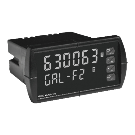
Model 122 Pulse Input Rate/Totalizer
Pulse, Open Collector, NPN, PNP, TTL, Switch Contact,
•
Sine Wave (Coil), Square Wave Inputs
Gate Function for Rate Display of Slow Pulse Rates
•
NEMA 4X, IP65 Front
•
Large Dual-Line 6-Digit Display, 0.60" & 0.46"
•
Isolated 24 VDC Transmitter Power Supply
•
Programmable Displays & Function Keys
•
Sunlight Readable Display Models
•
Rate Displayed as Units per Second, Minute, Hour, or Day
•
Total, Grand Total or Non-Resettable Grand Total
•
9-Digit Totalizer with Total Overflow Feature
•
K-Factor Calibration or Scale with up to 32-Point Linearization
•
Isolated 4-20 mA Output for Rate/Total/Grand Total
•
USB, RS-232 & RS-485 Serial Communication Options
•
Modbus
®
RTU Communication Protocol Standard
•
Free USB Programming Software & Cable
•
Max Machinery Inc
33A Healdsburg Ave
Healdsburg CA 95448 USA
Tel (707) 433-2662
Fax (707) 433-1818
Instruction Manual
www.maxmachinery.com
Advertisement
Table of Contents

Related Manuals for Max Machinery 122


Summary of Contents for Max Machinery 122
- Page 1 Model 122 Pulse Input Rate/Totalizer Instruction Manual Pulse, Open Collector, NPN, PNP, TTL, Switch Contact, • Sine Wave (Coil), Square Wave Inputs Gate Function for Rate Display of Slow Pulse Rates • NEMA 4X, IP65 Front • Large Dual-Line 6-Digit Display, 0.60" & 0.46"...
- Page 2 Anyone using this product for such applications does so at his/her own risk. Max Machinery Incorporated shall not be held liable for damages resulting from such improper use.
-
Page 3: Table Of Contents
Model 122 Pulse Input Rate/Totalizer Instruction Manual Table of Contents INTRODUCTION ------------------------------------------------------------ 5 ORDERING INFORMATION --------------------------------------------- 5 SPECIFICATIONS ---------------------------------------------------------- 6 General ------------------------------------------------------------------------------- 6 Rate Input --------------------------------------------------------------------------- 7 Rate/Totalizer ---------------------------------------------------------------------- 8 Isolated 4-20 mA Transmitter Output -------------------------------------- 9 Modbus ® RTU Serial Communications ---------------------------------- 10... - Page 4 Model 122 Pulse Input Rate/Totalizer Instruction Manual Multi-Point Calibration & Scaling -------------------------------------- 32 Scaling the Meter (SCALE) ---------------------------------------------- 32 Gate Function (Gate) ---------------------------------------------------- 33 Contact De-Bounce Filter (FiLter) ---------------------------------- 34 Time Base, Total Conversion Factor & Total Reset -------------- 35 Calibrating the Meter with External Source (Cal) ----------------- 36 Setting the Display Parameter &...
-
Page 5: Introduction
Figure 9: 4-20 mA Output Connections ..........18 INTRODUCTION The Model 122 is a multipurpose, easy to use pulse rate/totalizer ideal for flow rate, total, and control applications. It accepts pulse (e.g. ±40 mV to ±8 V), square wave (0-5 V, 0-12 V, or 0-24 V), open collector, NPN, PNP, TTL or switch contact signals. -
Page 6: Specifications
Model 122 Pulse Input Rate/Totalizer Instruction Manual SPECIFICATIONS Except where noted all specifications apply to operation at +25°C. General DISPLAY Upper display: 0.6" (15 mm) high, red LEDs Lower display: 0.46" (12 mm) high, red LEDs 6 digits: each (-99999 to 999999), with lead zero blanking. -
Page 7: Rate Input
Model 122 Pulse Input Rate/Totalizer Instruction Manual OVERVOLTAGE Installation Overvoltage Category II: CATEGORY Local level with smaller transient overvoltages than Installation Overvoltage Category III. ENVIRONMENTAL Operating temperature range: -40 to 65°C Storage temperature range: -40 to 85°C Relative humidity: 0 to 90% non-condensing... -
Page 8: Rate/Totalizer
Model 122 Pulse Input Rate/Totalizer Instruction Manual LOW-FLOW 0-999999 (0 disables cutoff function) CUTOFF DECIMAL POINT Up to five decimal places or none: d. d dddd, d. d ddd, d. d dd, d. d d, d. d , dddddd CALIBRATION May be calibrated using K-factor, internal calibration, or by applying an external calibration signal. -
Page 9: Isolated 4-20 Ma Transmitter Output
Model 122 Pulse Input Rate/Totalizer Instruction Manual TOTALIZER Calculates total based on rate and field programmable multiplier to display total in engineering units. Time base must be selected according to the time units in which the rate is displayed. TOTALIZER Totalizer rolls over when display exceeds 999,999,999. -
Page 10: Modbus ® Rtu Serial Communications
Model 122 Pulse Input Rate/Totalizer Instruction Manual ISOLATED Terminals I+ & R: 24 VDC ± 10%. May be used to power the 4- TRANSMITTER 20 mA output or other devices. Refer to Figure 6 on page POWER SUPPLY 16 and Figure 15 on page 18. -
Page 11: Compliance Information
Model 122 Pulse Input Rate/Totalizer Instruction Manual COMPLIANCE INFORMATION Safety UL & c-UL LISTED USA & Canada UL 508 Industrial Control Equipment UL FILE NUMBER E160849 FRONT PANEL UL Type 4X, NEMA 4X, IP65; panel gasket provided LOW VOLTAGE EN 61010-1:2010... -
Page 12: Safety Information
Model 122 Pulse Input Rate/Totalizer Instruction Manual Note: Testing was conducted on Model 122 meters installed through the covers of grounded metal enclosures with cable shields grounded at the point of entry representing installations designed to optimize EMC performance. Declaration of Conformity available at www.maxmachinery.com... -
Page 13: Installation
Model 122 Pulse Input Rate/Totalizer Instruction Manual INSTALLATION There is no need to remove the meter from its case to complete the installation, wiring, and setup of the meter for most applications. Instructions are provided for changing the transmitter power supply to output 5 or 10 VDC instead of 24 VDC, see page 15. -
Page 14: Figure 2: Meter Dimensions - Side View
Model 122 Pulse Input Rate/Totalizer Instruction Manual Mounting Dimensions Figure 2: Meter Dimensions - Side View Figure 3: Meter Dimensions - Top View... -
Page 15: Transmitter Supply Voltage Selection (P+, P-)
Model 122 Pulse Input Rate/Totalizer Instruction Manual Transmitter Supply Voltage Selection (P+, P-) All meters are shipped from the factory configured to provide 24 VDC power for the transmitter or sensor. If the transmitter requires 5 or 10 VDC excitation, the internal jumper J4 must be configured accordingly. -
Page 16: Connectors Labeling
Do not connect standard RJ45 cable, otherwise damage will occur to the equipment and the meter. Warning! Figure 5: Connector Labeling for Model 122 Power Connections Power connections are made to a two-terminal connector labeled POWER on Figure 5. The meter will operate regardless of DC polarity connection. -
Page 18: 4-20 Ma Output Connections
Model 122 Pulse Input Rate/Totalizer Instruction Manual 4-20 mA Output Connections Connections for the 4-20 mA transmitter output are made to the connector terminals labeled MA OUT. The 4-20 mA output may be powered internally or from an external power supply. -
Page 19: Setup And Programming
Model 122 Pulse Input Rate/Totalizer Instruction Manual SETUP AND PROGRAMMING The meter has been factory calibrated to read input • frequency in Hz (pulses/sec). The calibration equipment is certified to NIST standards. Use the K-Factor menu to match the rate/totalizer with •... -
Page 20: Meterview Pro Software
Model 122 Pulse Input Rate/Totalizer Instruction Manual MeterView Pro Software The meter can also be programmed using the PC-based MeterView Pro software included with the meter. This software can be installed on any Microsoft® Windows® (2000/XP/Vista/7/8/10) computer by connecting the meter’s onboard USB. The meter is powered by the USB connection, so there is no need to wire anything prior to programming the meter, though USB is intended only for meter configuration. - Page 21 Model 122 Pulse Input Rate/Totalizer Instruction Manual Double-click on the file named “MAStart.” The program will open a few windows and install two programs on your computer. Simply follow the onscreen instructions until you see one of the dialogs below. If you receive a “User Account Control” warning, click “Yes.”...
-
Page 22: Front Panel Buttons And Status Led Indicators
Model 122 Pulse Input Rate/Totalizer Instruction Manual Front Panel Buttons and Status LED Indicators Button Description Status Symbol Menu Alarm 1 – 4 indicator Right arrow/F1 Rate indicator Up arrow/F2 Total indicator Enter/F3 Grand Total indicator Total overflow Note: ▲... -
Page 23: Display Functions And Messages
Model 122 Pulse Input Rate/Totalizer Instruction Manual Display Functions and Messages The meter displays various functions and messages during setup, programming, and operation. The following table shows the main menu functions and messages in the order they appear in the menu. - Page 24 Model 122 Pulse Input Rate/Totalizer Instruction Manual Display Parameter Action/Setting Description Program time delay for total auto reset T dly Time delay Press Enter to reset total manually Manual Enter the Display menu dsplay Display Press Enter to assign the Upper display...
-
Page 25: Main Menu
Model 122 Pulse Input Rate/Totalizer Instruction Manual Main Menu The main menu consists of the most commonly used functions: Reset, Control, Setup, and Password. Press Menu button to enter Programming Mode then press the Up • arrow button to scroll through the main menu. -
Page 26: Setting Numeric Values
Model 122 Pulse Input Rate/Totalizer Instruction Manual Setting Numeric Values The numeric values are set using the Right and Up arrow buttons. Press Right arrow to select next digit and Up arrow to increment digit value. The digit being changed is displayed brighter than the rest. -
Page 27: Setting Up The Rate/Totalizer Meter (Setup)
Model 122 Pulse Input Rate/Totalizer Instruction Manual Setting up the Rate/Totalizer Meter (setup) The Setup menu is used to select: Enable or disable totalizer features Units for Rate, Total, and Grand Total Decimal point position Input Calibration Display parameter and intensity... -
Page 28: Setting The Input Signal (Input)
Model 122 Pulse Input Rate/Totalizer Instruction Manual Setting the Input Signal (Input) There is a switch, located to the right of the input connector, which must be configured according to the input level and type. Jumper J4 located inside the meter, behind the input signal connector, is used to select the excitation voltage (24 V*, 10 V or 5 V) which is supplied to the P+ and P- wiring terminals. -
Page 29: Setting The Input Units Or Custom Tags (Units)
Model 122 Pulse Input Rate/Totalizer Instruction Manual Setting the Input Units or Custom Tags (units) Enter the input unit or custom tag that will be displayed if alternating rate, total, or grand total and units is selected in the units menu, or d unit is selected as the lower display parameter. -
Page 30: Setting The Decimal Point (Dec Pt)
Model 122 Pulse Input Rate/Totalizer Instruction Manual Setting the Decimal Point (dEc pt) The decimal point may be set with up to five decimal places or with no decimal point at all. The rate, total, and grand total decimal points are independent. -
Page 31: K-Factor Calibration (Factor)
Model 122 Pulse Input Rate/Totalizer Instruction Manual Additional parameters, not needed for most applications, are programmed in the Advanced Features menu; see Advanced Features Menu, page 43. K-Factor Calibration (Factor) The meter may be calibrated using the K-Factor function. Most flowmeter manufacturers provide this information with the device. -
Page 32: Multi-Point Calibration & Scaling
Model 122 Pulse Input Rate/Totalizer Instruction Manual Multi-Point Calibration & Scaling The meter is set up at the factory for 2-point linear calibration. The number of points for multi-point calibration/scaling is set up in the Advanced Features menu. Up to 32 linearization points may be selected. -
Page 33: Gate Function (Gate)
Model 122 Pulse Input Rate/Totalizer Instruction Manual Error Message (Error) An error message indicates that the calibration or scaling process was not successful. After the error message is displayed, the meter reverts to input 2 during calibration or scaling, allowing the appropriate input signal to be applied or programmed. -
Page 34: Contact De-Bounce Filter (Filter)
Model 122 Pulse Input Rate/Totalizer Instruction Manual Gate Settings Slow Pulse Rate Low Gate* (sec) High Gate (sec) Min Freq** (Hz) 0.5000 10.0 0.1000 20.0 0.0500 100.0 0.0100 200.0 0.0050 400.0 0.0025 800.0 0.0012 999.9 0.0010 *The low gate setting corresponds to the display update rate and is used to stabilize the display reading with a fluctuating signal. -
Page 35: Time Base, Total Conversion Factor & Total Reset
Model 122 Pulse Input Rate/Totalizer Instruction Manual Time Base, Total Conversion Factor & Total Reset The time base, total conversion factor, and total reset menus are located in the Program menu. The total and grand total have their own independent settings. This... -
Page 36: Calibrating The Meter With External Source (Cal)
Model 122 Pulse Input Rate/Totalizer Instruction Manual Calibrating the Meter with External Source (Cal) To scale the meter without a signal source, refer to K-Factor Calibration (Factor) on page 31 or Scaling the Meter (SCALE) on page 32 The meter can be calibrated to display the process variable in engineering units by applying the appropriate input signal and following the calibration procedure. -
Page 37: Setting The Display Parameter & Intensity (Dsplay)
Model 122 Pulse Input Rate/Totalizer Instruction Manual Setting the Display Parameter & Intensity (dsplay) The upper display (line 1) can be programmed to display: Rate value Total or grand total Relay set points Max & min values Modbus input Display rate and units... -
Page 38: Display Setup Menu
Model 122 Pulse Input Rate/Totalizer Instruction Manual Display Setup Menu After setting up the input and the display, press the Menu button to exit programming and skip the rest of the setup menu. Press the Menu button again and the Up arrow to reach the Program menu and... -
Page 39: Front Panel Leds (Relay)
Model 122 Pulse Input Rate/Totalizer Instruction Manual Front Panel LEDs (rELAy) The LEDs on the front panel provide status indication for the following: Status Alarm 1 Alarm 2 Alarm 3 Alarm 4 The meter is supplied with four alarm points that include front panel LEDs to indicate alarm conditions. -
Page 40: Reset Menu (Reset)
Model 122 Pulse Input Rate/Totalizer Instruction Manual Reset Menu (reset) The Reset menu is used to reset the totals, maximum or minimum reading (peak or valley) reached by the process; both may be reset at the same time by selecting “reset high & low” (rst HL). -
Page 41: Protecting Or Locking The Meter
Model 122 Pulse Input Rate/Totalizer Instruction Manual Protecting or Locking the Meter Enter the Password menu and program a six-digit password. For instructions on how to program numeric values see Setting Numeric Values, page 26. Record the password for future reference. If appropriate, it may be recorded in the space provided. -
Page 42: Making Changes To A Password Protected Meter
Model 122 Pulse Input Rate/Totalizer Instruction Manual Making Changes to a Password Protected Meter If the meter is password protected, the meter will display the message Locd (Locked) when the Menu button is pressed. Press the Enter button while the message is being displayed and enter the correct password to gain access the menu. -
Page 43: Advanced Features Menu
Model 122 Pulse Input Rate/Totalizer Instruction Manual Advanced Features Menu To simplify the setup process, functions not needed for most applications are located in the Advanced Features menu. Press and hold the Menu button for three seconds to access the... -
Page 44: Advanced Features Menu & Display Messages
Model 122 Pulse Input Rate/Totalizer Instruction Manual Advanced Features Menu & Display Messages The following table shows the functions and messages of the Advanced Features menu in the order they appear in the menu. Display Parameter Action/Setting Enter Gate function menu... -
Page 45: Rounding Feature (Round)
Model 122 Pulse Input Rate/Totalizer Instruction Manual Display Parameter Action/Setting Program analog output parameters AoutPr Analog output programming Select source for the 4-20 mA output Source Source Program mA output for display overrange O-rang Overrange Program mA output for display... -
Page 46: Select Menu (Select)
Model 122 Pulse Input Rate/Totalizer Instruction Manual Select Menu (SElEct) The Select menu is used to select the signal input conditioner applied to the input (linear), low-flow cutoff, and analog output programming. The multi-point linearization is part of the linear function selection. -
Page 47: Low-Flow Cutoff (Cutoff)
Model 122 Pulse Input Rate/Totalizer Instruction Manual Low-Flow Cutoff (CutofF) The low-flow cutoff feature allows the meter to be programmed so that the often-unsteady output from a differential pressure transmitter, at low flow rates, always displays zero on the meter. -
Page 48: Programmable Function Keys User Menu (User)
Model 122 Pulse Input Rate/Totalizer Instruction Manual Programmable Function Keys User Menu (user) The User menu allows the user to assign the front panel function keys F1, F2, F3, F4 (digital input) and up to eight digital inputs to access most of the menus or to activate functions immediately (e.g. -
Page 49: Meter Operation
Model 122 Pulse Input Rate/Totalizer Instruction Manual METER OPERATION The meter accepts pulses (e.g. ±40mV to ± 8V), square wave (0-5, 0- 12V, or 0-24V), open collector NPN, PNP, TTL, or switch contact signals and displays these signals in engineering units from -99999 to 999999. -
Page 50: F4 Operation
Model 122 Pulse Input Rate/Totalizer Instruction Manual F4 Operation A digital input, F4, is standard on the meter. This digital input is programmed identically to function keys F1, F2, and F3. The input is triggered with a contact closure to COM, or with an active low signal. -
Page 51: Troubleshooting
Model 122 Pulse Input Rate/Totalizer Instruction Manual TROUBLESHOOTING The rugged design and the user-friendly interface of the meter should make it unusual for the installer or operator to refer to this section of the manual. However, due to the many features and functions of the meter, it’s possible that the setup of the meter does not agree with what an... -
Page 52: Reset Meter To Factory Defaults
Model 122 Pulse Input Rate/Totalizer Instruction Manual Reset Meter to Factory Defaults When the parameters have been changed in a way that is difficult to determine what’s happening, it might be better to start the setup process from the factory defaults. -
Page 53: Factory Defaults & User Settings
Model 122 Pulse Input Rate/Totalizer Instruction Manual Factory Defaults & User Settings The following table shows the factory setting for most of the programmable parameters on the meter. Next to the factory setting, the user may record the new setting for the particular application. - Page 54 Model 122 Pulse Input Rate/Totalizer Instruction Manual Parameter Display Default Setting User Setting Display 2 analog out 1000.0 Dis 2 Output 2 value 20.000 mA Out 2 Source analog Rate/process Source output Overrange output 21.000 mA O-rang Underrange output 3.000 mA...
-
Page 55: Troubleshooting Tips
Model 122 Pulse Input Rate/Totalizer Instruction Manual Troubleshooting Tips Symptom Check/Action Check power at power connector No display at all Meter is password-protected, enter Not able to change setup or correct six-digit password to unlock programming, Locd is displayed Check:... - Page 56 Model 122 Pulse Input Rate/Totalizer Instruction Manual How to Contact Max Machinery For Technical Support please Call: (707) 433-2662 Email: info@maxmachinery.com For the latest version of this manual please visit www.maxmachinery.com LIM6300MM_C SFT039 Ver 4.000 & up 08/16...
Need help?
Do you have a question about the 122 and is the answer not in the manual?
Questions and answers