Advertisement
Quick Links
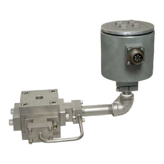
234 FLOW METER/TRANSMITTER
General Description . . . . . . . . . . . . . . . . . . . . . . . .Pg 2
Specifications . . . . . . . . . . . . . . . . . . . . . . . . . . . .Pg 3
Mechanical Installation . . . . . . . . . . . . . . . . . . . . . .Pg 4-5
Electronic Installation . . . . . . . . . . . . . . . . . . . . . . .Pg 6-12
Do's and Don'ts . . . . . . . . . . . . . . . . . . . . . . . . . . .Pg 13
Performance Curves . . . . . . . . . . . . . . . . . . . . . . .Pg 14-15
Max Machinery, Inc. reserves the right to make changes to the product in this
Instruction Manual to improve performance, reliability, or manufacturability.
Consequently, contact MMI for the latest available specifications and
performance data.
Although every effort has been made to ensure accuracy of the information
contained in this Instruction Manual, MMI assumes no responsibility for
inadvertent errors.
234-000-350 © 2005 Max Machinery, Inc.
INSTRUCTION MANUAL
TABLE OF CONTENTS
234-000-350 © 2005, Max Machinery, Inc.
( 1 )
Advertisement

Related Manuals for Max Machinery 234 Series


Summary of Contents for Max Machinery 234 Series
-
Page 1: Table Of Contents
Performance Curves ..... . .Pg 14-15 234-000-350 © 2005, Max Machinery, Inc. Max Machinery, Inc. reserves the right to make changes to the product in this Instruction Manual to improve performance, reliability, or manufacturability. -
Page 3: Specifications
Weather-tight Version ..... . . Designed to NEMA 4 / UL Class I, Group C & D Amphenol Connector Version ....Designed to NEMA 1 234-000-350 © 2005 Max Machinery, Inc. ( 3 ) -
Page 4: Mechanical Installation
Clean Plumbing: Before installing the flow meter, clean the inside of the pipe line with compressed air or steam. This is particularly important with new pipe. Typical Installation ( 4 ) 234-000-350 © 2005 Max Machinery, Inc. - Page 5 Mechanical Installation 234-000-350 © 2005 Max Machinery, Inc. ( 5 )
-
Page 6: Electronic Installation
Phase A and Phase B are each shown on the corresponding LEDs (‘OUT/∅A’ and ‘DIR/∅B’). If the combined output mode has been selected, the LED labeled ‘OUT/∅A’ shows the status of the pulse output channel, and the LED labeled ‘DIR/∅B’ indicates the direction. ( 6 ) 234-000-350 © 2005 Max Machinery, Inc. - Page 7 D9: This LED changes color (red to green or green to red) 4 times per revolution while the microprocessor is performing the calibration routine on the stator coils. When calibration is complete, it will turn off. See Calibration Section for more information on calibration procedures 234-000-350 © 2005 Max Machinery, Inc. ( 7 )
- Page 8 If the flow is stopped part way through a calibration, the blinking will stop and the calibration will not reach completion since it requires a fixed number of meter revolutions. In such a case, a new calibration should be done at a steady flow rate. ( 8 ) 234-000-350 © 2005 Max Machinery, Inc.
- Page 9 LED’s in the center of the board will pause. As soon as the calibration is complete, they will resume activity. 5. The calibration is now complete. Return S3 to the appropriate setting to get the desired number of output pulses per revolution. 234-000-350 © 2005 Max Machinery, Inc. ( 9 )
- Page 10 The graph below indicates typical conductor capacitance loads versus cable length for several types of cable. For instance, 1000 feet of 7 conductor #18 gauge stranded wire will put a 0.04 uF capacitive load on the output of the 234 Series Transmitters. ( 10 ) 234-000-350 © 2005 Max Machinery, Inc.
- Page 11 234 output signal. For instance, with 0.04uF load capacitance (1000 ft. shielded cable typ.) the rise/fall time is 10 uS. Consequently, the absolute maximum frequency the Model 234 could transmit would be 50 kHz (frequency = 1/time, where time includes the rise and fall times for one cycle). 234-000-350 © 2005 Max Machinery, Inc. ( 11 )
- Page 12 Electronic Installation ( 12 ) 234-000-350 © 2005 Max Machinery, Inc.
-
Page 13: Do's And Don'ts
D O N ’ T: Turn on the pump in a system filled with solidified material. Wait until the material is completely melted and use the flow meter bypass valve during start-up. 234-000-350 © 2005 Max Machinery, Inc. ( 13 ) -
Page 14: Performance Curves
Performance Curves ( 14 ) 234-000-350 © 2005 Max Machinery, Inc. - Page 15 Performance Curves 234-000-350 © 2005 Max Machinery, Inc. ( 15 )
Need help?
Do you have a question about the 234 Series and is the answer not in the manual?
Questions and answers