Table of Contents
Advertisement
SPLIT-TY PE, HEAT PUMP AIR CONDITIONERS
SPLIT-TY PE, AIR CONDITIONERS
SERVICE MANUAL
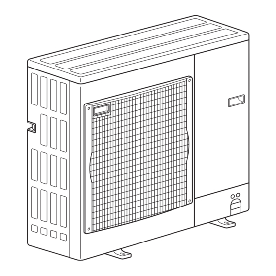
Outd oor unit
[ Mod el Names]
PU-P71VHA
PU-P71YHA
PU-P100VHA
PU-P100YHA
PU-P125YHA
PU-P140YHA
[ Serv ice Ref.]
Serv ice Ref. is on page 2.
R410A
PUH-P71VHA
PUH-P71YHA
PUH-P100VHA
PUH-P100YHA
PUH-P125YHA
PUH-P140YHA
CONTENTS
1. TECHNICAL CHANGES ................................... 2
2. REFERENCE MANUAL .................................... 4
3. SAFETY PRECAUTION ................................... 5
4. FEATURES ....................................................... 8
5. SPECIFICATIONS ............................................ 9
6. DATA .............................................................. 13
7. OUTLINES AND DIMENSIONS ..................... 17
8. WIRING DIAGRAM ........................................ 21
9. WIRING SPECIFICATIONS ........................... 26
10. REFRIGERANT SYSTEM DIAGRAM ................ 31
11. TROUBLESHOOTING ................................... 33
12. FUNCTION SETTING .................................... 74
14 EASY MAINTENANCE FUNCTION · · · · · · · · · · · · · 98
15. DISASSEMBLY PROCEDURE ..................... 105
16. PARTS LIST .................................................. 114
17. SERVICE PARTS LIST ................................. 120
J uly 2019
No.OC379
REVISED EDITION-J
Revision:
• Some descriptions have
been modified in REV ISED
EDITION-J.
OC37 9 REV ISED EDITION-H
is void.
Note:
• This manual describes ser-
vice data of the outdoor
units only.
Advertisement
Table of Contents

Related Manuals for Mitsubishi Electric PU-P125YHA 2.UK Series


Summarization of Contents
2 REFERENCE MANUAL
2-1. INDOOR UNIT’ S SERVICE MANUAL
Manual for indoor unit service procedures and specifications.
2-2. TECHNICAL DATA BOOK
Contains technical data for various unit models and their specifications.
3 SAFETY PRECAUTION
3-1. ALWAYS OBSERVE FOR SAFETY
General safety guidelines to follow before performing any service or maintenance.
3-2. CAUTIONS RELATED TO NEW REFRIGERANT
Specific precautions for handling R410A refrigerant, including tools and practices.
5 SPECIFICATIONS
OUTDOOR UNIT
Specifications and details related to the outdoor unit.
REFRIGERANT PIPING
Information and specifications for refrigerant piping work and connections.
6 DATA
6-1. REFILLING REFRIGERANT CHARGE (R410A : kg)
Details on refrigerant charge amounts for different piping lengths.
6-2. COMPRESSOR TECHNICAL DATA
Technical data for compressor models, including winding resistance.
6-3. NOISE CRITERION CURVES
Sound pressure level data for different models across various frequencies.
6-4. STANDARD OPERATION DATA
Operational data for different unit models under specific conditions.
7 OUTLINES AND DIMENSIONS
1 FREE SPACE (Around the unit)
Recommended clearance space around the unit for installation and airflow.
2 SERVICE SPACE
Required space for accessing the unit for maintenance and service.
3 FOUNDATION BOLTS
Details on securing the unit using foundation bolts and recommended heights.
4 PIPING-WIRING DIRECTIONS
Information on connecting pipes and wiring from different directions.
Piping Knockout Hole Details
Specifics on the dimensions and locations of piping knockout holes.
Example of Notes
Explanations for specific symbols or notes used in diagrams.
9 WIRING SPECIFICATIONS
9-1. FIELD ELECTRICAL WIRING (power wiring specifications)
Specifies wiring sizes, circuit ratings, and power supply requirements.
9-2. SEPARATE INDOOR UNIT/ OUTDOOR UNIT POWER SUPPLIES
Wiring diagrams for units with separate power supplies.
9-3. INDOOR – OUTDOOR CONNECTING CABLE
Specifications for the cable connecting indoor and outdoor units.
9-4. M-NET WIRING METHOD
Guidelines for wiring the M-NET communication system to avoid noise and errors.
11 TROUBLESHOOTING
11-1. TROUBLESHOOTING
General troubleshooting steps based on symptoms and observed conditions.
11-2. CHECK POINT UNDER TEST RUN
Procedures and checks to perform during the unit's test run phase, including error checks.
11-3. HOW TO PROCEED " SELF-DIAGNOSIS"
Steps for accessing and using the self-diagnosis function on the remote controller.
11-4. SELF-DIAGNOSIS ACTION TABLE
Table listing error codes, detection methods, cases, and recommended actions.
11-5. TROUBLESHOOTING OF PROBLEMS
Lists common operational problems with their potential causes and solutions.
11-6. HOW TO CHECK THE PARTS
Provides resistance values for testing various electrical components.
11-7. HOW TO CHECK THE COMPONENTS
Details resistance values for thermistors and their characteristic curves.
11-8. TEST POINT DIAGRAM
Illustrates test points on the outdoor controller board for diagnostics.
11-9. EMERGENCY OPERATION
Procedures for operating the unit manually in case of a malfunction.
11-10. FUNCTION OF SWITCHES, CONNECTORS AND JUMPERS
Explains the function and settings of various switches and connectors.
11-11. OPTIONAL PARTS A-control Service Tool [PAC-SK52ST]
Information on using the A-control service tool for diagnostics and settings.
12 FUNCTION SETTING
12-1. UNIT FUNCTION SETTING BY THE REMOTE CONTROLLER
General procedures for setting unit functions via remote controller.
12-1-1. Selecting functions using the wired remote controller
Step-by-step guide for wired remote controller function selection.
12-1-2. Selecting functions using the wired remote controller
Example procedure for setting room temperature detection.
12-1-3. Selecting functions using the wireless remote controller (Type C)
Procedure for setting functions using the wireless remote controller.
12-2. FUNCTION SELECTION OF REMOTE CONTROLLER 12-2-1. PAR-31MAA
Details on functions available via the PAR-31MAA remote controller.
13 MONITORING THE OPERATION DATA BY THE REMOTE CONTROLLER
13-1. HOW TO " MONITOR THE OPERATION DATA"
Steps to access and view operation data using the remote controller.
13-1-2. PAR-21MAA
Specific instructions for monitoring operation data using the PAR-21MAA remote controller.
14 EASY MAINTENANCE FUNCTION
14-1. SMOOTH MAINTENANCE
Details on using the smooth maintenance function for easier inspection.
14-2. REFRIGERANT LEAK CHECK (except RP170, 200)
Procedure for checking refrigerant leaks using the unit's function.
14-2-2. PAR-21MAA
Specific instructions for performing refrigerant leak checks with the PAR-21MAA remote controller.
15 DISASSEMBLY PROCEDURE
1. Removing the service panel and top panel
Details on removing the outer panels for access.
2. Removing the fan motor (MF)
Instructions for removing the fan motor assembly.
3. Removing the electrical parts box
Steps to remove the main electrical component housing.
4. Removing the thermistor <2-phase Pipe Temp., Cond./eva.> (TH6) and thermistor (TH3)
Procedure for removing these specific thermistors.
5. Removing the thermistor (TH4)
Instructions for removing the discharge thermistor.
6. Removing the solenoid valve coil (21S4), linear expansion valve coil (LEV) and solenoid valve coil (SV)
Procedure for removing multiple valve coils.
7. Removing the four-way valve
Steps to remove the four-way reversing valve.
8. Removing the linear expansion valve
Instructions for removing the LEV.
9. Removing the high pressure switch (63H)
Procedure for removing the high-pressure safety switch.
10. Removing the motor for compressor (MC)
Steps to remove the compressor motor.
11. Removing the Accumulator
Instructions for removing the refrigerant accumulator.
16 PARTS LIST ( non-RoHS compliant )
STRUCTURAL PARTS
List of the main external and frame components of the unit.
FUNCTIONAL PARTS
List of internal and operational components of the unit.
17 SERVICE PARTS LIST
STRUCTURAL PARTS
List of structural components with part numbers.
FUNCTIONAL PARTS
List of functional components with part numbers.
Need help?
Do you have a question about the PU-P125YHA 2.UK Series and is the answer not in the manual?
Questions and answers