
Related Manuals for Siemens SIPROTEC 4 7SS52


Summarization of Contents
Preface
Aim of this Manual
Describes the functions, operation, installation, and commissioning of the SIPROTEC 7SS52 V4 system.
Target audience
Identifies protection engineers, commissioners, and operation personnel.
Scope of validity of this manual
Specifies the manual's validity for SIPROTEC 7SS52 V4 system, firmware version 4.6.
Indication of Conformity
States compliance with EU directives and relevant standards for EMC and low-voltage.
Instructions and Warnings
Explains safety terms (DANGER, Warning, Caution, Note) and general safety rules for handling equipment.
Introduction
Overall Operation
Introduces the system's structure, digital processing, and bay/central unit functions.
Applications
Details the system's use in medium/high voltage stations and its modular design for extensions.
Features
Lists key features like multiprocessor system, digital processing, graphical planning, and communication interfaces.
Design and Connection System
General
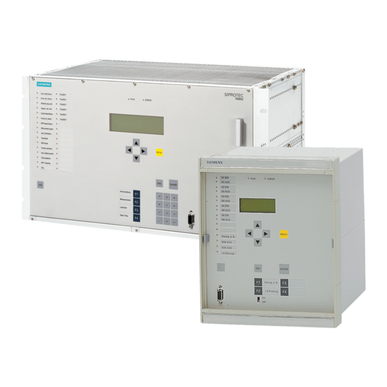
Outlines the system components: central unit, bay units, and data links (fiber-optic cables).
Central Unit
Describes the central unit's installation, design variants, front view, and module arrangement.
Bay Unit
Details the bay units' housing, front view, module arrangement, and design options.
Connection Method
Explains device connections for central and bay units, including terminals, connectors, and fiber-optic cables.
Getting Started
Matching the Control Voltage for the Binary Inputs and Inserting the Buffer Battery
Details how to configure control voltages for binary inputs and insert buffer batteries in central and bay units.
Setting up the Communication between the Central Unit and the Bay Unit
Guides on establishing communication via fiber-optic cables and matching addresses in DIGSI Manager.
Configuration
Creating a Project
Guides on creating a new project using DIGSI Manager for configuring the system.
Inserting Central Unit / Bay Units
Explains how to insert central and bay units into the project structure using DIGSI Manager's Device Catalog.
Plant Configuration
Details using DIGSI Plant Configuration to model the substation, draw busbars, and add elements.
Assigning Bay Units
Describes assigning configured bay units to Device Manager bay units for visualization and system startup.
Marshalling
Explains allocating information items to input/output components like binary inputs, outputs, and LEDs.
Settings
Covers configuring settings after assigning information items, including changing values and applying settings.
Concluding the Configuration
Guides on generating a report to verify parameter allocation and transmit settings to the central unit or bay units.
Configuration Notes
Provides key notes on configuring busbar arrangements, bay types, reserve bays, and CTs.
Functions
Busbar Protection
Details the busbar protection's basic principle, mode of operation, and measurement methods.
Check Zone
Explains the check zone's role in detecting short-circuits in all bays and its specific measurement system.
Circuit Breaker Failure Protection
Describes detecting circuit breaker failures during feeder or busbar short-circuits and the transfer trip mechanism.
End Fault Protection
Explains how end fault protection secures the zone between CTs and the circuit breaker when the breaker is open.
Supervisory Functions
Covers self-monitoring functions for hardware and software, ensuring high availability and security.
Oscillographic Fault Recording
Details the fault recording function, including data storage intervals, initiation, and evaluation.
Device
Summarizes annunciations not associated with specific protection functions, such as startup and operational status.
Power System Data
Explains the need for power system data to match the device's functions and how to set the rated system frequency.
Protection General
Provides general information required for busbar and breaker failure protection, including TRIP reset and local control.
Bay Unit
Refers to feeder-specific parameters for breaker failure protection, end fault protection, and general protection.
Integrated Operation of the Bay Unit
Describes choosing parameters for the UI language and specifying measured values for the standby display.
PC Port of the Bay Unit
Explains the PC port's function for device communication and setting data transmission formats and rates.
Fault Recording in the Bay Unit (”Local Fault Recording”)
Details the bay unit's fault recording function, including instantaneous value storage and initiation methods.
Scope of Protective Functions in the Bay Unit
Covers optional overcurrent protection as backup, its independence, and parameters for phase/earth current characteristics.
Power System Data of the Bay Unit
Explains how the system needs power data to match functions and how to set the CT starpoint orientation.
Overcurrent Protection in the Bay Unit
Describes the optional overcurrent protection as backup, its activation/deactivation, and characteristic settings.
User-Defined Annunciations
Explains how to define and allocate annunciations to alarm relays, LEDs, or trip relays using delay times.
Backup Breaker Failure Protection in the Bay Unit
Details the separate breaker failure protection initiated by the bay unit or via binary inputs.
Control During Operation
Overview
Introduces monitoring and operating bay units via DIGSI or the operator panel.
Reading Out Information
Explains how to retrieve annunciations, operational measured values, and fault data on-site or via DIGSI.
Controlling Device Functions
Covers options for interfering with protection functions during operation, including blocking and testing.
Feeder Shutdown and Commissioning
Provides instructions on putting bay units into service or shutting them down via DIGSI or the operator panel.
Maintenance Mode
Details how to perform maintenance mode individually for each feeder via DIGSI or the operator panel.
Plant Visualization
Explains using DIGSI Plant Visualization for on-line monitoring of the substation during operation.
Installation and Commissioning
Installation and Commissioning
Guides on installing and connecting central and bay units, and performing secondary value tests.
Checking the Connections
Outlines checks for external electrical and optical links, continuity, polarity, and auxiliary voltage.
Commissioning
Details essential commissioning steps, including configuration, checks, and tests.
Checks With Secondary Values
Explains performing checks with secondary values at current or default settings for the protection system.
Checks With Primary Values
Covers checking transformer polarity and other primary value tests to ensure correct operation.
Final Check of the Protection
Guides on final checks after testing, including parameter settings and ensuring proper operation.
Maintenance and Repair
Maintenance
Discusses maintenance-free electronic components and recommended periodic tests.
Fault Analysis
Explains analyzing disturbances caused by component failures or environmental conditions using diagnostic information.
Troubleshooting
Provides a recommended procedure for diagnosing and locating device defects using front panel LEDs and DIGSI.
Repair
Recommends refraining from module repair and outlines procedures for returning units or defective modules to the manufacturer.
Technical Data
General Data
Lists general parameters like TRIP command duration, overcurrent release, and busbar configuration limits.
General Device Data
Provides details on analog inputs/outputs, rated auxiliary voltage, power consumption, and binary inputs.
Dimensions
Presents mechanical dimensions for the central unit subrack and surface-mounted casing.
Dimensions
Central Unit
Shows mechanical dimensions for the central unit's subrack, including front, side, and top views.
Bay Unit
Displays dimensional drawings for the bay unit's 7XP2040-1 and 7XP2040-2 casings.
Appendix
Data for Selection and Ordering
Lists available component variants and their ordering codes for central and bay units.
Basis for Selection of the Stabilization Factor k
Explains the relationship between saturation time and stabilization factor, including burdening factor calculation.
Connection Diagrams
Provides connection diagrams for the central unit, including modular terminal blocks and FO interfaces.
Settings − Central Unit
Details jumper settings for ZPS modules and coding switch settings for the ZPS module in the central unit.
Jumper Settings − Bay Unit
Outlines jumper settings for PFE, SVW, SAF, AFE, EFE, and EFE_10 modules in bay units.
Protocol-Dependent Functions
Lists functions dependent on communication protocols like IEC 60870-5-103 and IEC 61850.
Parameter Listing - Central Unit
Provides a comprehensive list of all parameters, functions, setting options, default settings, and comments for the central unit.
Parameter Listing - Bay Unit
Lists all parameters, functions, setting options, and comments for the bay unit.
List of information - Central Unit
Details indications, alarms, and their IEC 60870-5-103 mappings and configurable matrix options.
List of Information - Bay Unit
Lists information items for bay units, including FNo., Description, Function, and IEC 60870-5-103 details.
Group Alarms - Central Unit
Lists group alarms for the central unit, their descriptions, FNo., logical functions, and relates them to bay units or bus zones.
Group Alarms - Bay Unit
Lists group alarms for the bay unit, their descriptions, FNo., and logical functions.
Measured Value List - Central Unit
Provides a list of measured values for the central unit, including descriptions, functions, and matrix configurations.
Measured Value List - Bay Unit
Lists measured values for bay units, including descriptions, functions, and IEC 60870-5-103 configurations.
Marshalling - Central Unit
Details marshalling of binary inputs and relay assignments for the central unit.
Marshalling - Bay Unit 7SS523
Outlines marshalling of binary inputs and signal relays for the 7SS523 bay unit.
Marshalling - Bay Unit 7SS525
Details marshalling of binary inputs and TRIP relays for the 7SS525 bay unit.
Navigation Tree - Central Unit
Provides an overview of parameter blocks and individual parameters in the central unit's navigation tree.
Navigation Tree of the Bay Unit
Shows the navigation tree for setting parameters in the bay units.
Abbreviations
Lists abbreviations used throughout the manual for technical terms and components.
References
Lists related documents and manuals for further information on SIPROTEC products and software.
Need help?
Do you have a question about the SIPROTEC 4 7SS52 and is the answer not in the manual?
Questions and answers