Table of Contents
Advertisement
Quick Links
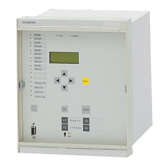
SIPROTEC
Distributed Busbar/ Breaker
Failure Protection
7SS522 V4.6
7SS523 V3.3
7SS525 V3.3
Manual
C53000-G1176-C182-3
Preface
Table of Contents
Introduction
Design and Connection System
Getting Started
Configuration
Functions
Control During Operation
Installation and Commissioning
Maintenance and Repair
Technical Data
Appendix
References
Index
1
2
3
4
5
6
7
8
9
A
Advertisement
Table of Contents


Need help?
Do you have a question about the SIPROTEC 7SS522 V4.6 and is the answer not in the manual?
Questions and answers