Table of Contents
Advertisement
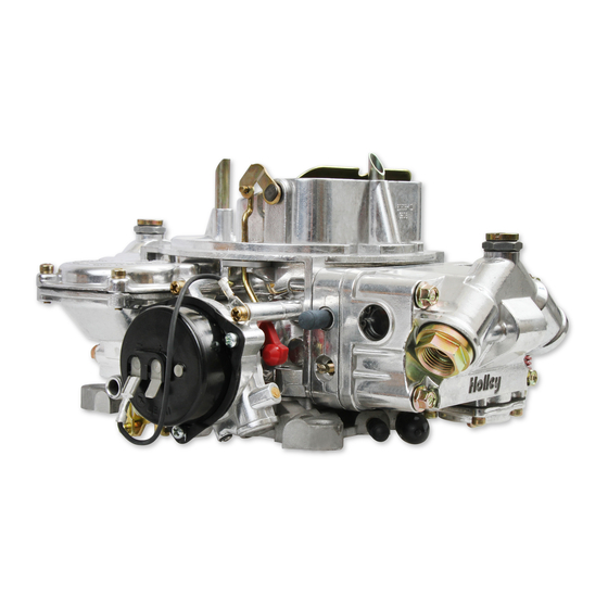
CARBURETOR
P/N 0-80508S, 0-80508SA, 0-80783C, 0-80459SA (electric choke)
P/N 0-3310S, 0-3310C & 0-3310SA (manual choke)
INSTALLATION, TUNING, AND ADJUSTMENT
MANUAL
199R9934-3
NOTE: These instructions must be read and fully understood before beginning
installation. If this manual is not fully understood, installation should
not be attempted. Failure to follow these instructions, including the
pictures may result in subsequent system failure.
Advertisement
Table of Contents

Related Manuals for Holley 0-3310C


Summary of Contents for Holley 0-3310C
- Page 1 CARBURETOR P/N 0-80508S, 0-80508SA, 0-80783C, 0-80459SA (electric choke) P/N 0-3310S, 0-3310C & 0-3310SA (manual choke) INSTALLATION, TUNING, AND ADJUSTMENT MANUAL 199R9934-3 NOTE: These instructions must be read and fully understood before beginning installation. If this manual is not fully understood, installation should not be attempted.
-
Page 2: Table Of Contents
TABLE OF CONTENTS: INTRODUCTION: ........................3 REMOVAL: ..........................3 INSTALLATION NOTES: ......................4 CHRYSLER APPLICATIONS ..........................4 FORD APPLICATIONS ............................4 GM APPLICATIONS .............................5 INSTALLATION: ......................... 5 CHOKE ADJUSTMENT: ......................9 IDLE MIXTURE NEEDLES: ....................... 10 FLOAT LEVEL CHECK AND ADJUSTMENT: ................. 11 VACUUM OPERATED SECONDARY THROTTLES: ............... -
Page 3: Introduction
INTRODUCTION: CONGRATULATIONS on your purchase of a Holley® carburetor! We feel that you have purchased the finest performance carburetor manufactured today. Should you need information or parts assistance, please contact our Technical Service Department at 1-270-781- 9741 or 1-866-GOHOLLEY, Monday through Friday, 7 a.m. to 5 p.m. CST. Please have the part number of the product you purchased on hand when you call To preserve warranty, these instructions must be read and followed thoroughly before and during installation. -
Page 4: Installation Notes
Unless you are replacing an existing Holley® carburetor (which already has a lever extension arm), you may need to purchase and install a throttle lever extension (Holley® P/N 20-7) on the carburetor. Remove the throttle stud and nut from the original carburetor. -
Page 5: Gm Applications
Remove the throttle cable ball and automatic transmission kickdown stud (if any) from the original carburetor, and mount these in similar locations on the Holley® throttle lever. If the original throttle cable is too large, a new throttle ball or stud is needed (Holley®... - Page 6 Reconnect the throttle and transmission kickdown linkage and throttle return spring (Holley® P/N 20-89). Operate the carburetor throttle lever by hand to assure the correct travel (no sticking or binding) by opening to wide open throttle and back to closed throttle several times.
- Page 7 CAUTION: The use of a quality in line fuel filter, such as Holley® P/N 162-523 is mandatory as a safeguard against possible flooding, which could result from unfiltered particles becoming lodged between the fuel inlet needle and its seat. This can result in fire if a spark is present or backfire occurs in the engine compartment.
- Page 8 15. With some air cleaner configurations, it may be necessary to use an air cleaner spacer to provide adequate clearance between the carburetor and the air cleaner. Holley® offers such a spacer (Holley® P/N 17-13). Depending on the overall height, obtain the proper length 1/4 x 20 stud and install in the carburetor airhorn.
-
Page 9: Choke Adjustment
CHOKE ADJUSTMENT: IMPORTANT: Your Holley® carburetor has been factory wet-flowed and calibrated. The “out of the box” settings should be very close for all adjustments. The following tuning section is included ONLY to aid you in fine tuning adjustments. Electric Choke You can control the choke operation by rotating the choke cap. -
Page 10: Idle Mixture Needles
IDLE MIXTURE NEEDLES: Idle mixture needles control the air/fuel mixture at idle. These have been preset at the factory and SHOULD NOT need any adjustments. However, if you feel that adjustment is necessary, you can use the following procedure to do so. When tuning the idle mixture, you’re actually tuning for the best manifold vacuum. -
Page 11: Float Level Check And Adjustment
FLOAT LEVEL CHECK AND ADJUSTMENT: FOR 0-80508S, 0-80783C, 0-3310C, 0-3310S: Primary and secondary float adjustments are set at the factory, but variations in fuel pressure could cause a change in these settings. The following procedure shows how to make these adjustments: Start the vehicle. - Page 12 FOR 0-80508SA, 0-80459SA, & 0-3310SA ONLY: NOTE: Do not try to remove the sight glasses. It takes special tools to install these and it is not recommended that they be removed. Primary and secondary float adjustments are set at the factory, but variations in fuel pressure could cause a change in these settings. To aid in adjustment of the float levels, clear sight glasses are installed from the factory.
-
Page 13: Vacuum Operated Secondary Throttles
Strange as it may seem, clipping springs actually increases spring rate and will delay opening. So in order to tune the secondaries follow the steps below. A secondary spring kit is available from your local Holley® retailer (Holley®... - Page 14 Figure 16 Figure 17 Remove the clip retaining the diaphragm plunger to the secondary throttle lever using a small flat-blade screwdriver (Figure 16). Remove the four screws securing diaphragm cover. Gently remove the cover. Take care as not to tear the diaphragm or loose the check ball (Figure 17). Change the spring.
-
Page 15: Jetting (Main Jets)
Carburetors are calibrated at 70° at sea level. Decrease the jet size primary and secondary, one number for every 2000 ft. increase in altitude. Holley® jets are broached, flowed, and stamped according to flow rate. NEVER drill jets, as this seriously alters flow characteristics. Stamped numbers are reference numbers and DO NOT indicate drill size. - Page 16 1801 Russellville Road Bowling Green, KY 42101 Technical Service: 1-866-GOHOLLEY Phone: 1-270-781-9741 Fax: 1-270-781-9772 For online help, please refer to the Tech Service section of our website: www.holley.com © 2005 Holley Performance Products, Inc. All rights reserved. 199R9934-3 Revision Date: 4-30-12...
Need help?
Do you have a question about the 0-3310C and is the answer not in the manual?
Questions and answers