Table of Contents

Advertisement

Quick Links

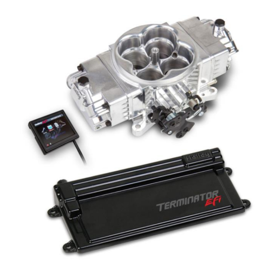
550-442 EFI Throttle Body w/ GM Trans Control - Polished
550-443 EFI Throttle Body w/ GM Trans Control – Hard Core Gray
550-445 EFI Throttle Body w/ GM Trans Control – Classic Gold Finish
FUEL INJECTION INSTALLATION MANUAL
Read this manual before using this product.
WARNING!
This instruction manual must be read and fully understood before beginning installation. If the instructions are not fully
understood, installation should not be attempted. Failure to follow the instructions may result in subsequent system failure and
could result in serious personal injury and/or property damage. Keep this manual.
For the safety and protection of you and others as well as your vehicle, only a trained mechanic having adequate fuel system
experience should perform the installation, adjustment, and repair.
While undertaking any work involving the fuel system, it is particularly important to remember one of the very basic principles of
safety: fuel vapors are heavier than air and tend to collect in low places where an explosive fuel/air mixture may be ignited by
any spark or flame resulting in property damage, personal injury, and/or death. Extreme caution must be exercised to prevent
spillage and thus eliminate the formation of such fuel vapors. All work involving this product and the fuel system generally
MUST be performed in a well-ventilated area. Do NOT smoke or have an open flame present near gasoline vapors or an
explosion may result.
Any components damaged due to failure to follow these instructions will not be covered by the warranty. Failure of any one
component does not constitute, nor does it justify, warranty of the complete system. Individual service items are available for
replacement of components. If assistance is required or if you need further warranty clarification, please call Holley Technical
Service at 1 (270) 781-9741 or (866) 464-6553.
1

Advertisement

Table of Contents
loading
Need help?

Need help?

Do you have a question about the Terminator Stealth EFI and is the answer not in the manual?

Questions and answers

Summary of Contents for Holley Terminator Stealth EFI

  • Page 1 Individual service items are available for replacement of components. If assistance is required or if you need further warranty clarification, please call Holley Technical Service at 1 (270) 781-9741 or (866) 464-6553.
  • Page 2: Table Of Contents

    30.5 Transmission ..................................34 30.5.1 Shifts ..................................34 30.5.2 WOT Shifts ................................35 30.5.3 Torque Converter Clutch (TCC) Parameters ......................36 30.5.4 Torque Converter Clutch (TCC) (Un) Lock ........................ 36 30.5.5 Line Pressure ................................37 31.0 SYSTEM SETUP .................................. 37 www.holley.com 1-866-464-6553...
  • Page 3: Introduction & System Requirements

    Any RTV silicone sealants used on the engine are sensor safe * Any square flange Holley type intake manifold will work. A spread bore intake manifold may work with no adapter as long as it is an aftermarket “universal flange” (meaning it has dual bolt patterns), and as long as it has enough material such that no vacuum leaks occur along the perimeter of the throttle body.
  • Page 4: Parts Identification

     Hardware and gaskets for mounting throttle body to 5/16-24 Nuts intake manifold Washers  Should be tightened down progressively in a criss- cross pattern to 5-7ft./lbs. Overtightening will damage throttle body! Flange Gasket 108-12 Manifold Flange Studs www.holley.com 1-866-464-6553...
  • Page 5 20-36 combinations Control Stud  Throttle Lever Ball 20-2 Throttle Lever Stud 20-37 Transmission 20-40  Used for various throttle and/or transmission Kickdown Stud combinations Lock Washers 1/4-28 Nuts Stealth Terminator Fuel Line 534-247 Assembly Transmission 558-405 Harness www.holley.com 1-866-464-6553...
  • Page 6: Tools Required For Installation

    The bung also must be on the top side of the tube so moisture cannot collect on the oxygen sensor. If there is an acceptable bung already present, go ahead and tighten the oxygen sensor supplied with your Sniper EFI in www.holley.com 1-866-464-6553...
  • Page 7: Coolant Temperature Sensor Installation

    It is best to drain the some of the coolant before the sensor is installed. Use thread sealer or a small amount of thread tape. Do not install the sensor in the thermostat housing, or in an area that will not see a constant flow of coolant. www.holley.com 1-866-464-6553...
  • Page 8: Throttle Body & Cable Bracket Installation

    NOTE: On late model GM and Ford overdrive transmissions with a lockup torque converter, make sure the lockup function is properly retained. Failure to do so will result in premature transmission failure. NOTE: On Chrysler vehicles, a lever extension will be needed, Holley PN 20-7. Van applications may require the use of throttle lever extension Holley PN 20-14.
  • Page 9: Vacuum Line Connections

    11) is intended as an overview of how the system should be wired. Remember, the main ECU power and ground must be connected directly to the battery post/terminal AFTER all other wiring installation has been performed. Do not attach the loose white or yellow wires, or ignition connector until you have referred to section 10.0 (Ignition Wiring). www.holley.com 1-866-464-6553...
  • Page 10: Harness Routing

    Connect the P1A and P1B connectors of the main harness into the ECU. About 18” from the ECU main connectors is a 40A Relay. This powers the injectors and fuel pump. There is also a 20 amp fuse for the injectors and fuel pump pre-installed in this location. www.holley.com 1-866-464-6553...
  • Page 11: Sensor Connections & Loose Wires

    SUPPORT, then TECH SERVICE, scroll down and click Resource Documents & Library. Go to the Fuel Injection tab and scroll down to the Holley EFI Wiring Manual. Black Wire = Chassis Ground Connect to a chassis ground point that has excellent connectivity with both the engine and battery.
  • Page 12: Ignition Wiring

    NOTE: When using this input, the EFI will NOT control the ignition timing of the engine. The timing will be based on the distributor initial, mechanical, and vacuum advance, just like it did with a carburetor. OPTION 1 WIRING: www.holley.com 1-866-464-6553...
  • Page 13 NOTE: When using this input, the EFI will NOT control the ignition timing of the engine. The timing will be based on the distributor initial, mechanical, and vacuum advance, just like it did with a carburetor. OPTION 2 WIRING: : “GM Small Cap HEI” Computer Controlled Distributor (Requires Holley Ignition Adapter PN 558-304) – OPTION 3 ...
  • Page 14 OPTION 3 WIRING W/ CAPACITIVE DISCHARGE BOX (Such as MSD 6AL) “Ford TFI” Computer Controlled Distributor (Requires Holley Ignition Adapter PN 558-305) – OPTION 4:  Ford Sequentially Injected 5.0-5.8L engines from 1987-1995 used this distributor. This option will allow the EFI to control the ignition timing.
  • Page 15: Additional Outputs

    It should be connected to the ground trigger of the relay. This wire is located in pin C of the 3 pin Input/Output connector and is Gray with a Green stripe. www.holley.com 1-866-464-6553...
  • Page 16: Transmission Wiring

    Turbine Speed Sensor – The 4L60E does not have a turbine speed sensor. It is located towards the front driver’s side on a 4L80E. Note that a 4L70E has one internally wired, but is not connected to the Holley harness. The turbine speed sensor is not used for any calculations in the ECU, just for monitoring purposes.
  • Page 17: Previous Installation Required

    The instructions are sequenced to get you up and running so you can enjoy your vehicle, then review some of the parameters that can be adjusted to fine tune your vehicle at a later time if desired. FOR ADVANCED TUNING INFORMATION PLEASE GO TO http://documents.holley.com/techlibrary_199r10751.pdf 15.0 INITIAL POWER-UP Turn the ignition key to the “run”...
  • Page 18: Handheld Navigation & Use

    The Wizard process will guide you through each selection step. There will be a question at the top. Select the proper response and select “Next” at the bottom. Selecting “Home” at any time will cancel the process. Next, select “Holley TBI” for the system type (Figure 18) Next, select “Terminator” for the TBI System Type Select which type of transmission you are using, 4L60 or 4L80, or “None”.
  • Page 19 HEI distributor or Ford TFI distributor. These are the only ignition distributors that allow the ECU timing control using the TERMINATOR™ system. All other ignition/distributor types must be a standard mechanical advance type used on any carbureted application. If you select “Yes”, proceed to step 10. If you select “No”, proceed to step 11. www.holley.com 1-866-464-6553...
  • Page 20: Tps Autoset

    “tach out” on the ignition box. Nothing should have been wired directly to the ignition coil. NOTE: If you are unsure of this selection, or wiring, contact Holley tech service. Damage to the ECU will result due to improper wiring.
  • Page 21: Transmission Setup

    WOT shift points. Figure 28 20.1.2 Speed Calc Four pieces of information will need to be entered via the 3.5 handheld to attain proper speedometer calibration when using Holley transmission control  Tire Diameter – From 10.0 to 70.0 inches (Example 26.4) ...
  • Page 22: Sensor Verification

    RPM signal. The engine should fire and run and come to an idle. If you do not get an RPM signal, there is an error in the wiring or system setup. Call Holley Tech service for advice.
  • Page 23: Setting Ignition Timing

    Whether you change the target idle or not, you need to set the throttle plates on the throttle body to an optimal position. To do so, with the engine running select the MONITOR tab. You will see the IDLE screen. Look at the “IAC Position” value. This value should be set www.holley.com 1-866-464-6553...
  • Page 24: Self-Tuning

    The display has a nice variety of pre-configured gauge screens and also allows the customization of them as well. There are also user- programmable caution and warning limits. The following reviews these areas. 27.1 Monitor Choose MONITOR from the HOME screen to access live telemetry and customizable gauge screen options. Figure 34 www.holley.com 1-866-464-6553...
  • Page 25: Multi-Gauge

    Drive by Wire: Gas Pedal Position, TB TPS #1, TB TPS #2, Pedal TPS #1, Pedal TPS #2, TB Position, Brake Pedal Position  Transmission: Gear, Speed, Line Pressure, Line Temperature, TCC Duty Cycle, TCC Lockup Status, Input Shaft Speed www.holley.com 1-866-464-6553...
  • Page 26: Diagnostics

    Up to three (3) Custom gauge layouts can be created on the 3.5 Touch Screen. Follow these steps to configure: Step 1: Choose ‘Dash Setup’ from the Multi-Gauge screen (Figure 39). Step 2: Choose the Dash number to be configured (Figure 40). Figure 39 Figure 40 www.holley.com 1-866-464-6553...
  • Page 27: Channels Scaling

    Terminator system. 29.1 File Choose FILE from the HOME screen to access ECU and 3.5 touch screen information. This is also where ECU logging and Global Folder (calibration file) transfer menus are located. Figure 45 www.holley.com 1-866-464-6553...
  • Page 28: Ecu Overview

    This menu will list any global folders that have been saved to the SD card. It will also allow you to download a global folder from the ECU to the SD card so that it may be opened on any Windows based PC with free Holley EFI software installed. Software may be downloaded http://www.holley.com/data/TechService/Technical/Holley%20EFI%202.2.0.3%20Setup.zip...
  • Page 29: Ecu Data Logging

    29.1.3 ECU Data Logging Holley HP and Dominator systems come standard with powerful data logging capabilities. Logging can be stopped and started via the 3.5 Handheld. The sampling rate is adjustable from 1 to 100 samples per second and can be changed by selecting ‘Setup’. Typically a high sampling rate is used for drag racing and a lower rate may be used for something such as road racing.
  • Page 30: Basic Tuning

    From the HOME SCREEN, select TUNING, and BASIC. There are six areas you can modify, BASIC FUEL, FUEL LEARN, BASIC IDLE, SPARK, DRIVE BY WIRE, and TRANSMISSION (with Drive by Wire and Transmission applying if applicable). These are reviewed below. Figure 59 www.holley.com 1-866-464-6553...
  • Page 31: Basic Fuel

    Changes the “accelerator pump” function of the fuel injection. Raising the number increases the amount of fuel added when the pedal is pushed. Lowering the number decreases the amount of fuel added when the pedal is pushed. It is highly recommended NOT to cha nge this until the ECU is allowed to perform self-tuning. www.holley.com 1-866-464-6553...
  • Page 32: Fuel Prime

    After the vehicle is driven under various operating conditions, and is running well, it is advised to disable learning, OR slow the Learn Speed to “Slow”. www.holley.com 1-866-464-6553...
  • Page 33: Learn Speed

    650-800 rpm are typical. Larger camshafts or aftermarket torque converters may require a slightly higher value to maintain proper idle quality while in gear. Figure 71 Figure 72 Selecting IDLE allows you to change the Target Idle Speed. IDLE SPEED: Adjust the idle speed to what is desired. www.holley.com 1-866-464-6553...
  • Page 34: Spark

    Figure 74 All Holley base tunes contain timing curves that will provide adequate engine operation, however the ignition timing at idle, cruise, and wide open throttle can be adjusted independently from each other to compensate for different engine combinations and geographical and climate extremes.
  • Page 35: Wot Shifts

    Figure 77 Figure 78 Figure 79 30.5.2 WOT Shifts Use this menu to choose the RPM at which the transmission will upshift at WOT. Each gear change may be adjusted independent of the others. Figure 80 Figure 81 www.holley.com 1-866-464-6553...
  • Page 36: Torque Converter Clutch (Tcc) Parameters

    ‘around-town’ driving if it is not desired. The Lock values should always be higher than the Unlock values. Adjustments to these can be done by using the graph. NOTE: See instructions for changing data in the GRAPH screen in the ‘Making Adjustments’ section. Figure 85 Figure 86 www.holley.com 1-866-464-6553...
  • Page 37: Line Pressure

    Values above 40-50% typically result in a line pressure too low for any throttle position, which may result in transmission damage. Figure 88 Figure 89 31.0 SYSTEM SETUP 31.1 System Tuning From the HOME MENU, select TUNING, and SYSTEM. There are four areas you can modify; OUTPUTS, ENGINE SETUP, IGNITION SETUP, and TRANSMISSION. Figure 90 www.holley.com 1-866-464-6553...
  • Page 38: Outputs

    Actual System Fuel Pressure: Enter the actual fuel system pressure for accurate fuel map & logging data. Wide Band O2 Sensor Type: Selects the type of wide band oxygen sensor used. If the software selection does not match the sensor being used damage to the WBO2 sensor will occur. www.holley.com 1-866-464-6553...
  • Page 39: Ignition Setup

    TBI Secondary Blend: If using a TBI with progressive linkage, this value is used to start the ramp-in of the secondary fuel injectors as the rear throttle plates open. Enter the TPS when the rear throttle plates start to open. This is typically 36% for a Holley throttle body unit.
  • Page 40: Advanced Tuning

    32.2 Closed Loop CLOSED LOOP OPERATION relies on WBO2 sensor readings. The Holley EFI system uses these readings to analyze ‘real time’ running conditions. The data obtained by the ECU is then used trim fuel flow to achieve the targeted air fuel ratio (AFR).
  • Page 41: Advanced Learn

    O2 sensor reading, LEARN COMPENSATION LIMITS are the percentage of change that is allowed to actually be saved as a modifier to the fuel map. www.holley.com 1-866-464-6553...
  • Page 42: Advanced Idle

    IAC moves from a position of 0% (fully closed, no air added) to 100% (fully open, maximum air flow). NOTE: Contact Holley Tech Support if you have any questions regarding IAC settings. Selecting IAC RAMPDOWN brings up the following menu with four choices, IAC HOLD POSITION, IAC RAMP DECAY, IAC RAMP START, and IAC KICK.
  • Page 43: Iac Speed

    IAC Startup Hold Time: This is the amount of time that the IAC will remain at the “IAC Parked Position”.  IAC Startup Decay Time: This is the amount of time for the IAC to decay from the “IAC Parked Position” back to its “Target Idle” position. It is a linear decay. www.holley.com 1-866-464-6553...
  • Page 44: Idle Spark

    Idle spark is a feature active only when the ECU is controlling timing. When enabled, the ECU modifies commanded timing at idle to help maintain the target idle speed. Figure 114 Figure 115 NOTE: This feature should be disabled when checking base timing with a timing light! If not disabled rev the engine to approximately 2000 RPM when syncing timing. www.holley.com 1-866-464-6553...
  • Page 45: Appendix 2.0 Sensor Diagnostics And Statuses

    TPS Diagnostics – The following are shown for the “TPS” parameter. Text Description Error! If you see an error, contact Holley Tech Service. NeedCal TPS Autoset needs to be performed. Closed Loop Diagnostics – Shows status of closed loop operation.
  • Page 46 Figure 116 Figure 117 www.holley.com 1-866-464-6553...
  • Page 47 Figure 118 Figure 119 www.holley.com 1-866-464-6553...
  • Page 48 Figure 120 Figure 121 Holley Technical Support: 270-781-9741 or 866-464-6553 © 2016 Holley Performance Products, Inc. All rights reserved. Tous Droits Réservés. 199R11137 Revision Date: 4-1-21 www.holley.com 1-866-464-6553...

This manual is also suitable for:

550-443550-442550-445

Table of Contents