
Related Manuals for Holley Sniper EFI Stealth 4500


Summary of Contents for Holley Sniper EFI Stealth 4500
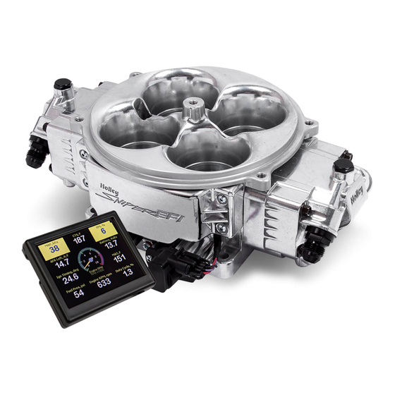
- Page 1 Sniper Stealth 4500 (550-841 Shiny, 550-842 Black, & 550-843 Gold) Holley Sniper EFI FUEL INJECTION INSTALLATION MANUAL...
- Page 2 Failure of any one component does not constitute, nor does it justify, warranty of the complete system. Individual service items are available for replacement of components. If assistance is required or if you need further warranty clarification, please call Holley Technical Service at 1 (270) 781-9741.
-
Page 3: Table Of Contents
TIMING CONTROLLED IGNITION SYSYEM WIRING ....................20 Timing Control Preface: ............................20 MSD (Magnetic) Distributor [Timing Control] ......................20 Holley Dual Sync Distributor [Timing Control] ......................25 Sniper EFI HyperSpark Distributor [Timing Control] ....................31 HANDHELD NAVIGATION ............................32 Possible Screens ..............................32 INITIAL EFI SETUP .............................. - Page 4 Basic Idle ................................. 47 Spark ..................................48 SYSTEM TUNING ................................ 48 Outputs ..................................49 Engine Setup ................................50 Sniper Setup ................................50 Ignition Setup ................................51 Static Timing ................................51 ADVANCED TUNING ..............................52 IAC Rampdown ................................ 54 Idle Spark ................................55 Idle Speed ................................
-
Page 5: Introduction & System Requirements
(more fuel flow may be needed for higher horsepower engines). When selecting a pump, and lines, be sure each component is designed to perform at high pressure. Holley offers a variety of fuel pumps, hoses and accessories to complete your installation. -
Page 6: Parts Identification
PARTS IDENTIFICATION ITEM # IMAGE DESCRIPTION SERVICE P/N NOTES Use of leaded fuel will degrade sensor. Prolonged will require periodic Bosch Wide Band 554-155 replacement. Oxygen Sensor Mounting procedure below is critical for system performance Requires 3/4” hole to be drilled ... -
Page 7: Preparing The Throttle Body For Installation
PREPARING THE THROTTLE BODY FOR INSTALLATION If the Sniper EFI will be used on a N/A engine, no changes need to be made to the throttle body. Draw through Supercharger Applications: When using the Sniper EFI on a draw through boosted application (I.E. positive displacement blower such as an 8/71), the throttle body must be converted to read manifold pressure from a remote source that sees manifold pressure. -
Page 8: Oxygen Sensor Installation
If the O2 cable has melted it is not something fixed under warranty and will require the unit to be sent back to Holley to be repaired at customer cost. Ensure the location for the sensor is at the angle in Figure 1. This will help prevent condensation in the exhaust tubing from entering the sensor. -
Page 9: Coolant Tempature Sensor Installation
Figure 3 Figure 4 Figure 5 NOTE: Never run the engine with the oxygen sensor installed if it is not plugged in and powered by the ECU, or it will be damaged. If you need to plug the hole temporarily, use an O2 sensor plug or a spark plug with an 18mm thread. -
Page 10: Fuel System Connections
Connect fuel feed and return hose. It is mandatory to use an external fuel pressure regulator and feed both front and rear fuel injector covers. Holley 12-848 or 12-851 are the recommended bypass fuel pressure regulator based on how much HP the application makes. Reference Figure 3 & 4 for plumbing diagrams and recommended fuel system components. -
Page 11: Ecu Wiring Overview
ECU WIRING OVERVIEW The Sniper EFI throttle body comes with sensors pre-wired for easy installation. The illustrated diagram below is intended as an overview of how the system should be wired. Remember, the main ECU power and ground must be connected directly to the battery AFTER all other wiring installation has been performed. -
Page 12: Basic Wiring Installation
Dark Brown Tach Output Used to drive an aftermarket tachometer Digital Gauge Output Used to drive Holley EFI analog gauges via 554-130 Gauge Module 8 Pin Connector – Mating Harness PN 558-492, 8 wires are populated. Color Labeled Name Function... -
Page 13: General Wiring Reference
GENERAL WIRING REFERENCE An EFI system depends heavily on being supplied a clean and constant voltage source. The grounds of an electrical system are just as important as the power side. Sniper EFI contains multiple processing devices that require clean power and ground sources. The wiring for them must be installed in such a manner that they are separated from “dirty”... -
Page 14: Connecting Sniper Efi Touchscreen Lcd To Sniper Efi
Connecting Sniper EFI Touchscreen LCD to Sniper EFI Connect the Sniper EFI Handheld to the main harness. This is a simple plug and play connection. If you are going to permanently leave the handheld in the vehicle, you will need to find a factory grommet in your firewall to pass the Display CAN bus connector through and secure the excess wire away from hazards. - Page 15 UNUSED WIRES As you finish the installation of your Sniper EFI you will likely have unused wires. These wires need to be properly taken care of before installation is considered complete or you may end up with problems down the road. You have two options on how to properly handle these wires.
- Page 16 Option 2: Trim and Wrap Wire Required tools: Wire cutters Adhesive heat shrink tubing Heat source (heat gun or other) Procedure Disconnect the battery terminals. Cut the end of the wire so that there is no bare copper showing. NOTE: Make sure you leave enough length on the wire that you will have room to crimp or solder it at a later date should the need arise.
-
Page 17: Non Timing Controlled Ignition System Wiring
NON TIMING CONTROLLED IGNITION SYSTEM WIRING Coil (-) [no timing control] This Yellow wire marked “Coil-” is an RPM input wire used for the following applications: A stock type mechanical advance distributor with a stock inductive ignition coil. Examples of this would be any older style points distributor. -
Page 18: Ignition Box Tach Output (No Timing Control)
Ignition Box Tach Output (No Timing Control) This requires use of the Ignition Adapter / Purple Wire that comes packaged with the main power harness. If you are using an aftermarket Capacitive Discharge (CD) ignition system such as a MSD, Accel, or others, you need to connect to the “Tach Out”... - Page 19 For additional instructions on how to setup a Sniper EFI using a CD ignition box, please reference this helpful video. https://www.youtube.com/watch?v=1EFiTBQ9DvI...
-
Page 20: Timing Controlled Ignition Sysyem Wiring
Holley recommends that those who wish to use the Sniper’s timing control feature first get the engine running without timing control. Splitting the timing control into a secondary process will add very little time to the total install, but could significantly help with trouble shooting, should it be needed. - Page 21 Distributor Lock Out Procedure Remove the rotor from the distributor. Remove the advance components including the springs, weights, lock nut, and the advance stop bushing from the advance assembly. Remove the roll-pin from the drive gear and then remove the gear from the housing shaft. Slide the shaft up approximately two inches out of the housing.
- Page 22 Connect the 2 wire connector on the distributor to the matching connector on your Sniper EFI power harness. Connect the white points output wire either to the Holley coil driver module or the Points input wire on your ignition box. Refer to the following wiring diagrams to complete the wiring.
- Page 23 For additional and alternative instructions on how to setup a Sniper EFI using a magnetic distributor, please reference this helpful video. https://www.youtube.com/watch?v=oBSiyeg4XCU&feature=youtu.be...
- Page 24 MSD (Mag) Distributor w/ Direct Drive Coil MSD (Mag) DISTRIBUTOR W/ CAPACATIVE DISCHARGE BOX (Such as MSD 6AL)
-
Page 25: Holley Dual Sync Distributor [Timing Control]
Sniper installations utilizing timing control. NOTE: It is recommended that you use a Holley Dual Sync distributor if you are using a Hall Effect input for your rpm signal. However, Sniper EFI will accept a 1x per fire hall effect signal from other devices. It is up to the customer to verify compatibility and proper installation procedure with anything other than a Holley Dual Sync distributor. - Page 26 Next, connect the 10 pin distributor connector to the Holley #558-493 adapter harness. Note: If you have not already completed your installation of the 558-493 harness please do so before continuing. Reconnect the battery cable(s), leaving the coil disconnected at this time.
- Page 27 Clockwise Rotor Rotation: (See chart to determine what direction your distributor rotates.) For engines that have the rotor rotating clockwise, turn Slowly turn the housing clockwise until the Crank LED goes OFF (Figure 3). the housing until the rotor contact is pointed at the black crank position sensor (Figure 2).
- Page 28 Counter-Clockwise Rotor Rotation: (See chart to determine what direction your distributor rotates.) For engines that have the rotor rotating counter-clockwise, turn Slowly turn the housing counter-clockwise until the Crank LED goes the housing until the rotor is pointed at the black crank position OFF (Figure 6).
- Page 29 For additional instructions on how to setup a Sniper EFI using a Holley Dual Sync Distributor, please reference this helpful video. https://www.youtube.com/watch?v=O5_089Q39CA...
- Page 30 Direct-Drive Coil WIRING W/ Holley Dual Sync Distributor Holley Dual Sync Distributor WIRING W/ and CAPACATIVE DISCHARGE BOX (Such as MSD 6AL) HOLLEY DUAL SYNC DISTRIBUTOR PINOUT: If custom wiring the distributor, use the following pinout: Connector Location Channel...
-
Page 31: Sniper Efi Hyperspark Distributor [Timing Control]
Sniper EFI HyperSpark Distributor [Timing Control] Sniper EFI HyperSpark distributors are designed to work with Sniper EFI systems for timing control. The design of these distributors includes a Hall Effect Sensor for Crank Signal. The precision machined shutter wheel design ensures accurate timing, even at very high engine speeds making them an excellent choice for Sniper installations utilizing timing control. -
Page 32: Handheld Navigation
HANDHELD NAVIGATION Possible Screens The 3.5” handheld utilizes a touch screen display. All navigation is done through “touching” an icon or button on the screen. The following is an overview of the different types of adjustment screens that are used in the display, and that may be utilized when tuning or making selections. - Page 33 Graph Options: Digitally: Selecting this option enables slider bar adjustment of individual data points on the graph or the entire curve. Graphically: Selecting this option enables single point or whole curve adjustment. A stylus may be used to select and drag data on the graph screen. Entire Curve: Selecting this will ‘lock’...
-
Page 34: Initial Efi Setup
INITIAL EFI SETUP Calibration Wizards Turn the ignition key to the “run” position. This should apply 12+ volts to the Pink wire in the ECU harness and will power the Sniper EFI Touch Screen LCD. The Home Screen (figure below) should appear. The Home screen contains icons which will navigate to different functional features of the 3.5”... - Page 35 To Run the Wizard see the following: STEP 1 Select WIZARD from the main menu - Select your Sniper system type STEP 2 - Press Next - Select the number of cylinders your engine has STEP 3 - Press Next - Use the slider bar to input the displacement of your engine STEP 4...
- Page 36 Coil (-) [no timing control] CD Ignition Box [no timing control] STEP 7 Magnetic Distributor Holley Dual Sync Distributor HyperSpark Distributor - Press Next -Select power adder type None for Naturally Aspirated Engines ...
- Page 37 - Use the slider bar to input the desired target AFR WOT without boost. (Turbo and Supercharged STEP 11 Power Adder Types Only) - Press Next - Use the slider bar to input the desired target AFR Offset per 7 lbs of boost. (Turbo and Supercharged Poweradder Types Only) STEP 12 The 4 boxes at the bottom show the AFR targets...
-
Page 38: Sensor Verification
Sensor Verification Before starting the vehicle, verify that all of the sensors are reading properly. To do this, turn the ignition key off, and cycle it back on. You should hear the fuel pump come on and run for 5 seconds. Fuel Prime occurs 2.5 seconds after key-on (which is also the amount of time it takes for the 3.5”... -
Page 39: Prestart Checklist
“Syncing”, indicating the ECU is syncing with the RPM signal for an instant, then show an RPM signal. The engine should fire and run and come to an idle. If the engine does not start please use the flow chart at the end of this Manual. If issue still continues then Call Holley Tech service for advice. -
Page 40: Ignition Timing Check (Without Timing Control)
Current Learn, % - This is the percentage of fuel the ECU is adding or subtracting to the base fuel map. This is not a progress bar. A value with a minus (-) sign in front indicates the ECU is removing fuel from the base fuel map. A value with no minus sign indicates the ECU is adding fuel to the base fuel map. -
Page 41: Ignition Timing Check (Ecu Controlling Timing)
Ignition Timing Check (ECU Controlling Timing) Have a timing light handy as the first step will be positioning the distributor. Turn the key ON to power the system and go to Tuning -> System -> Static Timing. This screen allows you to set the distributor exactly where the Sniper ECU needs it to be positioned to operate the timing. -
Page 42: Throttle Blade Adjustment
THROTTLE BLADE ADJUSTMENT Once engine has warmed up above 160 degrees the throttle blade angle can be set. It is critical for the engine to be above 160 degrees F before setting the throttle blade angle. From the Home screen, Select the Tuning Icon. Then Select Basic and then the Basic Idle Icons. This will allow you to set your basic Engine Idle Speed when engine is up to temperature. -
Page 43: System Setup
From the Home Screen, Select the Tuning Icon. Then Select the System Icon. Next Select the Ignition Setup Icon. Here is where you can change you Ignition settings. Following are examples of what the specific default ignition configurations look like in the handheld. Coil - CD Box Magnetic Holley Dual Sync HyperSpark... -
Page 44: Basic Tuning
The Basic Tuning allows changes to the Air/Fuel Ratio’s, changes to Ignition Timing if the Sniper is configured to as a Magnetic distributor or a Holley Dual Sync ignition setup , Closed Loop and Learning, and basic idle speed. The Advanced Tuning is typically not needed. -
Page 45: Target Afr
Target AFR Allows changes to the Target Air/Fuel ratio at idle, cruise, wide open throttle & boost offset if applicable. The following are typical values and some tuning notes. Idle Air/Fuel Ratio – Typically between 13.5 and 15.0. Engines with larger cams may need a richer setting for smoothest idle. -
Page 46: Fuel Prime
Fuel Prime Fuel prime is an option that is enabled by default in all of the base calibrations. The fuel prime function injects a small shot of fuel into the intake manifold when the ignition is turned on, wetting the intake and allowing the engine to start much quicker. -
Page 47: Learn Enable/Disable
Learn Enable/Disable The LEARN Enable / Disable menu turns the Self Tuning “On” and “Off”. If enabled, self-tuning is performed. Learning should be enabled when an engine is first run with the Sniper EFI and the tuning process is occurring. After the vehicle is driven under various operating conditions, and is running well, it is advised to limit the amount of learning that can occur in the Advanced Learn menu. -
Page 48: Spark
Spark All Holley base tunes contain timing curves that will allow the engine to run, however the ignition timing at idle, cruise, and wide open throttle can be adjusted independently from each other to compensate for different engine combinations, elevation and climate extremes. -
Page 49: Outputs
Outputs The OUTPUT screen allows for the Fan #1 and Fan #2 ON and OFF temperatures to be adjusted. The ON temp needs to always be a higher value than the OFF temp. Use a difference of at least 5 degrees so they aren’t cycling excessively. In Sniper EFI these are ground outputs that should be wired to trigger the fan relays. -
Page 50: Engine Setup
Engine Setup These parameters should be all properly pre- set when you went through the Wizard Process. They can be modified here, and if the Key Icon is next to the Parameter, the change will not take place until the ignition is cycled. Number of Cylinders: Adjust the number of cylinders of the engine KPA to Engine Vacuum at Sea Level Engine Displacement: Enter the actual size of the engine... -
Page 51: Ignition Setup
Ignition Setup These parameters should be all properly pre- set when you went through the Wizard Process. They can be modified here. Note: If the Key Icon is next to the Parameter, the change will not take place until the ignition is cycled. Ignition Type: Change the calibration for different ignition setups Reference Angle (Timing Control Configurations Only): This is the value in crank degrees of the distributor's crank pulse. -
Page 52: Advanced Tuning
ADVANCED TUNING From the HOME MENU, select TUNING, and ADVANCED. There are five areas you can modify; ADV FUEL, CLOSED LOOP, ADV. LEARN, ADV. IDLE and LAUNCH. These are reviewed below. The Advanced Tuning areas typically won’t ever be needed to be changed. However, after getting used to the Sniper EFI system, there may be some fine tuning of various parameters that you’d like to perform. - Page 53 Closed Loop CLOSED LOOP OPERATION relies on WBO2 sensor readings. The Sniper EFI system uses these readings to analyze ‘real time’ running conditions. The data obtained by the ECU is then used trim fuel flow to achieve the targeted air fuel ratio (AFR).
-
Page 54: Iac Rampdown
NOTE: Contact Holley Tech Support if you have any questions regarding IAC settings. Selecting IAC RAMPDOWN brings up the following menu with four choices, IAC HOLD POSITION, IAC RAMP DECAY, IAC RAMP START, and IAC KICK. These are reviewed below: ... -
Page 55: Idle Spark
IAC Speed This menu is used to select the type of IAC motor application that is being used. This selection drives the background parameters that control the IAC motor. These parameters have been fine tuned for each of these applications, eliminating the need for the user to perform further modifications IAC Startup These parameters control the position of the IAC when the engine is cranking and immediately after it starts. -
Page 56: Idle Speed
Idle Speed Idle speed will allow you to change the target idle speed for different coolant temperatures. Advanced 2 Launch Sniper EFI has a secondary rev limiter and the ability to retard the ignition timing after a trigger point. These functions are typically used for drag racing. -
Page 57: Sniper Efi Monitor
Idle Primarily intended for race engines that have open exhaust and false oxygen sensor readings at low exhaust velocities, this modifies the VE number in the fuel table. Race Cam calibrations have closed loop off at idle. This option is only available for calibrations that have closed loop off below a certain RPM, and is a VE modifier. This will allow a user to lean or richen the engine when below the closed loop RPM threshold. -
Page 58: Multi-Gauge
Multi-Gauge Sniper EFI Multi-Gauge shows live data in a gauge format. Below are an example of the Sensors Multi-Gauge and the Air/Fuel Ratio Multi-Gauge Changing Monitor Channel Scaling You can change the scale and background warning activation thresholds on the data monitor channels Press the “Monitor”... - Page 59 iv. Caution Max: Where Gauge Warning will become Red on High Side v. Normal Min: Where Gauge Warning will become Yellow on Low Side vi. Normal Max: Where Gauge Warning will become Yellow on High Side Example: Air/Fuel Ratio: Large Round Sweep from 8.0-18.5AFR Red Background when Leaner than 16.0 and Richer than 10.5 Yellow Background when between 15.0-16.0 AFR...
-
Page 60: Custom Configuring Dash 1 Dash 2 Or Dash 3
Custom Configuring Dash 1 Dash 2 or Dash 3 Dash 1, Dash 2 & Dash 3 are user customizable dashes using the predetermined channels in the Sniper EFI. The customer can choose how to setup these Monitor Screens to their own personal preference. Press the “Monitor”... -
Page 61: Advanced Tables On Handheld
ADVANCED TABLES ON HANDHELD The configurations in the advanced tables must be setup using the Sniper EFI Software. Once those are configured limited number of parameters may be adjusted in the handheld. Please read the Sniper EFI software instructions to properly setup the Advanced Tables in the software and determine what certain parameters do. - Page 62 Basic : Closed Loop / Learn This menu enables or disables closed loop operation. There is typically no reason to turn off closed loop operation unless you Closed loop suspect an oxygen sensor problem and want to disable the enable/disable sensor.
- Page 63 Tuning : System The OUTPUT screen allows for the Fan #1 and Fan #2 ON and OFF temperatures to be adjusted. The ON temp needs to always be a higher value than the OFF temp. Use a difference of at Fan #1 On least 5 degrees so they aren’t cycling excessively.
- Page 64 This gets the commanded static timing value that has been set previously, if user navigated away from static timing check screen and the ignition has not been cycled. Static Timing This sets the commanded timing to the chosen value This clears the static timing value Clear Close This closes the Static Timing menu...
- Page 65 Advanced : Closed Loop This menu enables or disables closed loop operation. There is typically no reason to turn off closed loop operation unless you suspect an oxygen sensor problem and want to disable the sensor. Closed loop enable Note: Self-Tuning requires closed loop operation to function / disable The maximum percentage the ECU is allowed to deviate (+/-) from the base fuel calibration in order to maintain the commanded target...
- Page 66 Advanced : Adv Idle This is the position the IAC motor will “hold” or “freeze” at when the TPS moves above idle (when TPS becomes greater than 0%). If IAC hold position it is too high, the engine RPM will “hang” and not return to idle. This is the time (in seconds) it takes for the IAC to return to the IAC Ramp Decay target idle range of movement.
- Page 67 Advanced : Launch Rev Limiter #1 Enable or Disable Rev Limiter #1 Enable Rev Limiter #1 RPM set point for Rev Limiter #1 2-Step Rev Limiter #1 Choose the input wire used on the 10-pin harness Input Launch Retard Enable or Disable the programmable launch retard Enable Launch Retard Use this to edit the launch retard curve...
- Page 68 Super Sniper : Nitrous If using Sniper for Nitrous Control, this will Enable or Disable the Disable Stage Minimum RPM required for NOS activation Min RPM Maximum RPM allowed for NOS activation. Any RPM above this Max RPM will turn off the stage. Activation This will delay the activation by the amount selected.
- Page 69 Super Sniper : Advanced These tables require software for initial configuration and are Enable/Disable intended for advanced EFI users. Table Name These tables require software for initial configuration and are (display only) intended for advanced EFI users. Table Type (display These tables require software for initial configuration and are only) intended for advanced EFI users.
-
Page 70: Datalogging & File Transfers
Pressing the Diag Type icon will allow a user to change the Diagnostics type recorded in the datalog. Holley Tech Service may ask for this to be changed. This example will start a log as soon as the engine RPM Exceeds 3000 RPM. -
Page 71: Downloading Global Configuration From Sniper Efi Throttle Body To Sd Card
Downloading Global Configuration from Loading Calibration into Sniper EFI ECU Sniper EFI Throttle Body to SD card: Press “File” icon from the Main Menu 1. Press “File” icon from the Main Menu Press the “Global Configs” Icon 2. Press the “Global Configs” Icon Highlight the Configuration you would like to load into the Sniper EFI (making it highlight in Blue). -
Page 72: Laptop Support
Put the saved Configuration from SD card (in Saved GCF folder) in the Sniper EFI Config File Folder, this is in your Documents folder if the Sniper Software was installed in the default location This PC > Documents > Holley > Sniper > Config Files Open Sniper EFI Software, and click “Open Config File” icon... -
Page 73: Viewing Datalog With Sniper Efi Software
Choose the saved Configuration you are wanting to open Calibration can be viewed and Modified using the Sniper Software. It can be saved directly to the SD card or to the Config Files folder. If saving to the Config Files Folder a copy of the tune will also need to be placed on the SD Card to Transfer it to the Sniper EFI via the Handheld. -
Page 74: Troubleshooting
“Open” Button. The data log will open to be viewed. TROUBLESHOOTING Troubleshooting Guide Holley has created a troubleshooting flow chart to help customers with issues they may be having. This can be found on www.holley.com. Here is a direct link to the Troubleshooting Guide. http://documents.holley.com/199r11369.pdf Sensor Verification Verify all sensors are reading properly on the handheld. - Page 75 System is in closed loop operation. Learn Status – Shows status of learn mode. Text Description NoLearn Learning is not active. Learng Learn is in an active state. © 2018 Holley Performance Products. All Rights Reserved. Tous Droits Réservés. 199R11322 Date: 4-30-18...
Need help?
Do you have a question about the Sniper EFI Stealth 4500 and is the answer not in the manual?
Questions and answers