Table of Contents
Advertisement
Quick Links
HP E1312A/E1412A User's Manual and SCPI Programming Guide
Warranty ....................................................................................................................... 9
Safety Symbols ........................................................................................................... 10
WARNINGS ............................................................................................................... 10
HP E1312A Declaration of Conformity ..................................................................... 11
HP E1412A Declaration of Conformity ..................................................................... 12
Reader Comment Sheet .............................................................................................. 13
Chapter 1
HP E1312A and HP E1412A Multimeter Module Setup ......................................... 15
Using This Chapter ..................................................................................................... 15
General Information ............................................................................................ 15
Setting the Module Address Switch............................................................................ 16
Interrupt Priority ......................................................................................................... 17
Setting the Line Frequency Reference........................................................................ 17
Checking the Line Frequency Reference ............................................................ 17
Multimeter Functional Connections .................................................................... 19
Initial Operation .......................................................................................................... 22
Chapter 2
HP E1312A/E1412A Multimeter Application Information ..................................... 25
Using This Chapter .................................................................................................... 25
Measurement Tutorial................................................................................................. 25
DC Voltage Measurements ......................................................................................... 25
Thermal EMF Errors ........................................................................................... 25
Loading Errors (dc volts) .................................................................................... 26
Leakage Current Errors ....................................................................................... 26
Rejecting Power Line Noise Voltages ................................................................ 27
Common Mode Rejection (CMR) ....................................................................... 27
Noise Caused by Magnetic Loops ....................................................................... 28
Noise Caused by Ground Loops .......................................................................... 28
Resistance Measurements ........................................................................................... 29
4-Wire Ohms Measurements ............................................................................... 29
Power Dissipation Effects ................................................................................... 31
Settling Time Effects ........................................................................................... 31
Errors in High Resistance Measurements ........................................................... 31
Making High-Speed DC and Resistance Measurements ..................................... 31
DC Current Measurement Errors ................................................................................ 32
True RMS AC Measurements..................................................................................... 32
Crest Factor Errors (non-sinusoidal inputs) ........................................................ 33
Loading Errors (ac volts) ..................................................................................... 34
AC Measurements Below Full Scale .................................................................. 34
Function and Range Change Internal Offset Correction ..................................... 34
Low-Level Measurement Errors ......................................................................... 35
AC Turnover Errors ............................................................................................ 35
AC Current Measurement Errors ................................................................................ 36
Making High-Speed AC Voltage or Current Measurements...................................... 36
Contents
Edition 4
Contents
1
Advertisement
Table of Contents

Related Manuals for HP E1412A


Summary of Contents for HP E1412A
-
Page 1: Table Of Contents
HP E1312A Declaration of Conformity ..............11 HP E1412A Declaration of Conformity ..............12 Reader Comment Sheet ....................13 Chapter 1 HP E1312A and HP E1412A Multimeter Module Setup ......... 15 Using This Chapter ..................... 15 General Information .................... 15 Setting the Module Address Switch................16 Interrupt Priority ...................... - Page 2 Querying the Delay Time ..................51 The Sample Count ....................51 Checking the Sample Count ................51 HP E1312A and HP E1412A Multimeter Application Examples ......52 HP VTL Software (VISA) ................... 52 Example Programs ....................52 Making Multimeter Measurements ..............53 Synchronizing the Multimeter With a Switch Module ........
- Page 3 Chapter 3 Multimeter Command Reference (continued) CALCulate ........................73 :AVERage:AVERage? ..................74 :AVERage:COUNt? .................... 74 :AVERage:MAXimum? ..................74 :AVERage:MINimum? ..................74 :DB:REFerence ....................75 :DB:REFerence? ....................75 :DBM:REFerence ....................75 :DBM:REFerence? ....................75 :FUNCtion ......................76 :FUNCtion? ......................76 :LIMit:LOWer ..................... 77 :LIMit:LOWer? ....................
- Page 4 Chapter 3 Multimeter Command Reference (continued) FETCh? ........................98 INITiate........................99 [:IMMediate] ....................... 99 INPut......................... 100 :IMPedance:AUTO ................... 100 :IMPedance:AUTO? ..................100 MEASure ........................101 :CURRent:AC? ....................102 :CURRent[:DC]? ....................103 :FREQuency? ....................104 :FRESistance? ....................105 :PERiod? ......................106 :RESistance? ......................
- Page 5 Chapter 3 Multimeter Command Reference (continued) [SENSe:] (continued) FREQuency:VOLTage:RANGe ................ 129 FREQuency:VOLTage:RANGe? ..............129 FREQuency:VOLTage:RANGe:AUTO ............130 FREQuency:VOLTage:RANGe:AUTO? ............130 FRESistance:APERture ..................131 FRESistance:APERture? ................... 131 FRESistance:NPLC ................... 132 FRESistance:NPLC? ..................132 FRESistance:RANGe ..................133 FRESistance:RANGe? ..................133 FRESistance:RANGe:AUTO ................134 FRESistance:RANGe:AUTO? ................
- Page 6 *TST? ........................ 166 *WAI ......................... 166 SCPI Command Quick Reference ................167 Appendix A HP E1312A and HP E1412A Multimeter Specifications ........171 DC Characteristics ....................171 AC Characteristics ....................174 Frequency and Period Characteristics............... 177 General Specifications ....................179 To Calculate Total Measurement Error ..............
- Page 7 Calibration Errors ....................190 Appendix C Measurement Speed and Accuracy Trade-offs ............193 HP E1312A/E1412A Special Function and Range Commands (Non-SCPI ) ..193 Speed Advantage Using the Special Non-SCPI Commands (F1-F4 and R1-R7) ..................194 HP E1312A/E1412A Resolution Using Special Functions and Ranges....195 Resolution Example ..................
- Page 8 Notes: Contents...
-
Page 9: Edition 4
FITNESS FOR A PARTICULAR PURPOSE. 8. HP will be liable for damage to tangible property per incident up to the greater of $300,000 or the actual amount paid for t he product that is the subject of the claim, and for damages for bodily injury or death, to the extent that all such damages are determined by a court of competent jurisdiction to have been directly caused by a defective HP product. -
Page 10: Safety Symbols
Documentation History All Editions and Updates of this manual and their creation date are listed below. The first Edition of the manual is Edition 1. The Edition number increments by 1 whenever the manual is revised. Updates, which are issued between Editions, contain replacement pages to correct or add additional information to the current Edition of the manual. -
Page 11: Hp E1312A Declaration Of Conformity
Supplementary Information: The product herewith complies with the requirements of the Low Voltage Directive 73/23/EEC and the EMC Directive 89/336/EEC and carries the "CE" marking accordingly. Tested in a typical configuration in an HP B-Size VXI mainframe. Jim White, QA Manager... -
Page 12: Hp E1412A Declaration Of Conformity
Supplementary Information: The product herewith complies with the requirements of the Low Voltage Directive 73/23/EEC and the EMC Directive 89/336/EEC (inclusive 93/68/EEC) and carries the "CE" marking accordingly. Tested in a typical configuration in an HP C-Size VXI mainframe. Jim White, QA Manager... -
Page 13: Reader Comment Sheet
Please fold and tape for mailing Reader Comment Sheet HP E1312A/E1412A 6½-Digit Multimeter User’s Manual and SCPI Programming Guide Edition 4 You can help us improve our manuals by sharing your comments and suggestions. In appreciation of your time, we will enter you in a quarterly drawing for a Hewlett-Packard Palmtop Personal Computer (U.S. -
Page 15: Hp E1312A And Hp E1412A Multimeter Module Setup
• Initial Operation General Information • The HP E1312A is not recommended for use in the HP E1300A or HP E1301A B-size mainframe. • The HP E1312A (VXI B-size) and HP E1412A (VXI C-size) Multimeters are VXIbus message-based slave devices. -
Page 16: Setting The Module Address Switch
The logical address switch factory setting is 24. Valid addresses are from 1 to 254 for static configuration (the address you set on the switch) and address 255 for dynamic configuration. The HP E1312A and HP E1412A support dynamic configuration of the address. This means the address is set programmatically by the resource manager when it encounters a module with address 255 that supports dynamic configuration. -
Page 17: Interrupt Priority
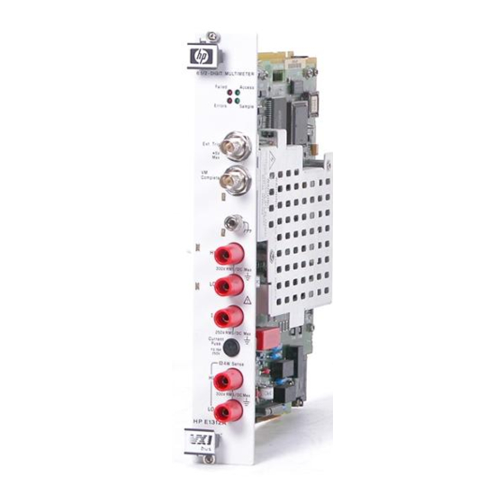
Interrupt Priority The HP E1312A and HP E1412A Multimeters are VXIbus interrupters. However, there is no interrupt priority level setting to be made on the module. Interrupt priority level, setup, and activation are configured on the resource manager which is the interface to the VXIbus and contains any instrument drivers required to communicate with a VXI module. - Page 18 Figure 1-2. Multimeter Measurement Terminals 18 HP E1312A and HP E1412A Multimeter Module Setup Chapter 1...
-
Page 19: Multimeter Functional Connections
Multimeter Functional Connections Figure 1-3. Switch Module Analog Bus Connections Figure 1-4. Frequency or Period Measurement Connections Chapter 1 HP E1312A and HP E1412A Multimeter Module Setup... - Page 20 Figure 1-5. Voltage Measurement Connections Figure 1-6. Voltage Ratio (Vdc) Measurement Connections 20 HP E1312A and HP E1412A Multimeter Module Setup Chapter 1...
- Page 21 Figure 1-7. 2-Wire Ohms Measurement Connections Figure 1-8. 4-Wire Ohms Measurement Connections Chapter 1 HP E1312A and HP E1412A Multimeter Module Setup...
-
Page 22: Initial Operation
To program the Multimeter using SCPI, you must select the interface address and SCPI commands to be used. General information about using SCPI commands is presented at the beginning of Chapter 3. See the HP 75000 Series C Installation and Getting Started Guide for interface addressing. Note This discussion applies only to SCPI (Standard Commands for Programmable Instruments) programming. - Page 23 /* end of main */ /*** Error handling function ***/ void err_handler (ViSession dmm, ViStatus err) char buf[1024] = {0}; viStatusDesc (dmm, err, buf); printf ("ERROR = %s/n", buf); return; Chapter 1 HP E1312A and HP E1412A Multimeter Module Setup...
- Page 24 Notes: 24 HP E1312A and HP E1412A Multimeter Module Setup Chapter 1...
-
Page 25: Hp E1312A/E1412A Multimeter Application Information
HP E1312A and HP E1412A Multimeter Application Examples. Measurement Tutorial The HP E1312A and HP E1412A are capable of making highly accurate measurements. In order to achieve the greatest accuracy, you must take the necessary steps to eliminate potential measurement errors. This section describes common errors found in measurements and gives suggestions to help you avoid these errors. -
Page 26: Loading Errors (Dc Volts)
30°C. This current generates small voltage offsets dependent upon the source resistance of the device-under-test. This effect becomes evident for a source resistance of greater than 100kΩ, or when the multimeter's operating temperature is significantly greater than 30°C. 26 HP E1312A/E1412A Multimeter Application Information Chapter 2... -
Page 27: Rejecting Power Line Noise Voltages
(and their harmonics) will average out to approximately zero. The HP E1312A and HP E1412A provide three A/D integration times (1, 10 and 100PLCs) to reject power line frequency noise (and power-line frequency harmonics). Power line frequency defaults to 60Hz unless you specifically set it to 50Hz with the command. -
Page 28: Noise Caused By Magnetic Loops
This will reduce or eliminate any voltage difference between the devices. Also make sure the multimeter and device-under-test are connected to the same electrical outlet whenever possible. 28 HP E1312A/E1412A Multimeter Application Information Chapter 2... -
Page 29: Resistance Measurements
Resistance Measurements The HP E1312A and HP E1412A offer two methods for measuring resistance: 2-wire and 4-wire ohms. For both methods, the test current flows from the input HI terminal and then through the resistor being measured. For 2-wire ohms, the voltage drop across the resistor being measured is sensed internal to the multimeter. -
Page 30: Removing Field Wiring Resistance Errors In 2-Wire Ohms Measurements
DUT. Make a 2-wire ohms resistance measurement. READ? Enter lead resistance value into computer. The NULL value is subtracted from the measurement to more accurately provide the DUT resistance. 30 HP E1312A/E1412A Multimeter Application Information Chapter 2... -
Page 31: Power Dissipation Effects
25µW 10MΩ 500nA 2.5µW Settling Time Both the HP E1312A and HP E1412A have the ability to insert automatic measurement settling delays with the TRIG:DEL command. These delays are Effects adequate for resistance measurements with less than 200pF of combined cable and device capacitance. -
Page 32: Dc Current Measurement Errors
True RMS AC Measurements True responding multimeters, like the HP E1312A and HP E1412A, measure the “heating” potential of an applied signal. Unlike an “average responding” measurement, a true... -
Page 33: Crest Factor Errors (Non-Sinusoidal Inputs)
In general, the greater the crest factor, the greater the energy contained in higher frequency harmonics. All multimeters exhibit measurement errors that are crest factor dependent. HP E1312A and HP E1412A crest factor errors are shown in the AC Characteristics... -
Page 34: Loading Errors (Ac Volts)
Loading Errors In the ac voltage function, the input of the HP E1312A and HP E1412A appears as a 1MΩ resistance in parallel with 100pF of capacitance. The (ac volts) cabling that you use to connect signals to the multimeter will also add additional capacitance and loading. -
Page 35: Low-Level Measurement Errors
Because of the capacitance between the input LO terminal and earth (approximately 200 pF for the HP E1312A and HP E1412A), the source will experience different loading depending on how the input is applied. The magnitude of the error is dependent upon the source's response to this loading. -
Page 36: Ac Current Measurement Errors
(or period) of an input following a dc offset voltage change. You must allow the multimeter's input dc blocking capacitor to fully settle before making frequency measurements. 36 HP E1312A/E1412A Multimeter Application Information Chapter 2... -
Page 37: Measurement Configuration
CONFigure AC Signal Filter The HP E1412A Multimeter has three different ac filters which enable you to either optimize low frequency accuracy or achieve faster ac settling times for ac voltage or ac current measurements. Only these functions use the ac filter. -
Page 38: Resolution
“Sense” terminals. • Set the resolution using the following commands: function range resolution CONFigure:< > < >|MIN|MAX,< >|MIN|MAX MEASure:< function >? < range >|MIN|MAX,< resolution >|MIN|MAX function resolution [SENSe:]< > < >|MIN|MAX 38 HP E1312A/E1412A Multimeter Application Information Chapter 2... -
Page 39: Integration Time
4½-digits, 100mS for 5½-digits or 1 second for 6½-digits of resolution. • Set integration time using the following commands: [SENSe:]< function >:NPLC < number > s are not applicable for the functions (NPLC FREQ function seconds [SENSe:]< >:APER < > Chapter 2 HP E1312A/E1412A Multimeter Application Information... -
Page 40: Autozero
You can set the range using any of the following commands: function range resolution CONFigure:< > < >|MIN|MAX|DEF,< >|MIN|MAX|DEF function range resolution MEASure:< >? < >|MIN|MAX|DEF,< >|MIN|MAX|DEF function range [SENSe:]< >:RANGe < >|MIN|MAX function [SENSe:]< >:RANGe:AUTO OFF|ON 40 HP E1312A/E1412A Multimeter Application Information Chapter 2... -
Page 41: Math Operations (Calculate Subsystem)
0 and ±120% of the highest range, for the present function. • Clearing the value. The null value is stored in volatile memory; NULL the value is cleared when power is removed, after resetting the multimeter or after a function change. Chapter 2 HP E1312A/E1412A Multimeter Application Information... -
Page 42: Db Measurements
• Clearing the relative value. The relative value is stored in volatile memory; the value is cleared when power is removed, after the module is reset or after a function change. 42 HP E1312A/E1412A Multimeter Application Information Chapter 2... -
Page 43: Dbm Measurements
The calculate state must be enabled before you can store a value in the Reference Resistance Register. Set math function to DBm. CALCulate:FUNCtion DBm Enable math operation. CALCulate:STATe ON CALCulate:DBM:REFerence < value > Store a dBm reference. Chapter 2 HP E1312A/E1412A Multimeter Application Information... -
Page 44: Limit Function
STAT:QUES[:EVEN]? questionable register and determine what failure occurred. Sending this command also clears the questionable data register (or send a Clear Status command to clear the register before testing begins). *CLS 44 HP E1312A/E1412A Multimeter Application Information Chapter 2... -
Page 45: Triggering The Multimeter
MEASure CONFigure commands. However, you will need the information in this section to take advantage of the flexibility of the HP E1312A/E1412A trigger system when using the command. CONFigure The multimeter’s trigger system synchronizes measurements with specified internal or external events. These events include software trigger commands, negative-going edges on the VXIbus trigger lines (TTLT0 - TTLT7), and negative-going pulses on the multimeter's external trigger (“Trig”) BNC... -
Page 46: The Trigger Source
Within the HP 75000 Series C mainframes, the instrument whose trigger source is “ ” and was the last instrument addressed to listen will respond to the HP-IB Group Execute Trigger. The *TRG command differs from GET because it is sent to a specific instrument not a group of instruments. -
Page 47: External Triggering
The multimeter takes one reading (or the number specified by ) immediately after a command. SAMPle:COUNt READ? INITiate The multimeter takes only one reading immediately following a MEAS? command. • See the triggering process diagram in Figure 2-1 on page 45. Chapter 2 HP E1312A/E1412A Multimeter Application Information... -
Page 48: Bus Triggering
• You can also trigger the multimeter from the HP-IB interface by sending the IEEE-488 Group Execute Trigger (GET) message. The multimeter must be in the wait-for-trigger state. Send a GET from a... -
Page 49: Checking The Trigger Count
May require INIT, monitor the status byte for completion (standard event bit 0), FETC? to transfer readings to the output buffer (vs. READ?). enter statement Enter readings into computer. Chapter 2 HP E1312A/E1412A Multimeter Application Information... -
Page 50: Default Delays
Default Trigger Delays for AC Voltage and AC Current (all ranges): AC Filter Trigger Delay 3Hz - 300kHz filter 7.0sec 20Hz - 300kHz filter 1.0sec 200Hz - 300kHz filter 600ms Default Trigger Delay for Frequency and Period: 1.0s 50 HP E1312A/E1412A Multimeter Application Information Chapter 2... -
Page 51: Querying The Delay Time
Sample Count • The present sample count (1 through 50,000) if neither is specified. • The minimum sample count available (1) if is specified. • The maximum sample count available (50,000) if is specified. Chapter 2 HP E1312A/E1412A Multimeter Application Information... -
Page 52: Hp E1312A And Hp E1412A Multimeter Application Examples
HP E1312A and HP E1412A Multimeter Application Examples This section contains example programs that demonstrate several applications using the HP E1312A or HP E1412A Multimeter. The examples described in this section list only the SCPI commands (see Chapter 3, “Multimeter Command Reference”) required to perform the application. -
Page 53: Making Multimeter Measurements
486 IBM compatible computer running Windows 3.1. The computer has an HP 82341 HP-IB interface and HP SICL/Windows 3.1 and Windows NT for HP-IB software. The VXI modules were loaded in a VXI C-size mainframe using an HP E1406A or B-size mainframe with HP E1306A Command Module as resource manager connected to the computer via the HP 82341 HP-IB card. - Page 54 Enter reading into computer. • Comments You must provide a TTL external trigger signal to the HP E1312A or HP E1412A front panel “Trig” input BNC. Measurements are triggered by low pulses of this signal. Each trigger results in 10 readings.
- Page 55 30 measurements; 10 samples for each of three internal triggers. • command causes the readings to be transferred to the FETCh? output buffer and you must provide the I/O construct to retrieve the readings and enter them into the computer. Chapter 2 HP E1312A/E1412A Multimeter Application Information...
- Page 56 FETCh? You must be careful when using the commands. INITiate FETCh? Internal memory stores a maximum of 512 readings; the oldest readings exceeding 512 are lost. 56 HP E1312A/E1412A Multimeter Application Information Chapter 2...
-
Page 57: Synchronizing The Multimeter With A Switch Module
Synchronizing the This program example demonstrates how to synchronize the multimeter with a switch module. For the HP E1412A it uses the TTL triggers from the Multimeter With a VXI backplane to trigger the multimeter and advance the channel scan list. - Page 58 This example monitors the switch module’s status system. The switch module’s status system (HP E1476A) is shown in Figure 2-4. This example program enables the switch's “Scan Complete” bit to allow it to set the OPR bit in the switch's status byte when the scan is finished. The program repeatedly reads the switch module's status byte until the OPR bit gets set which returns a status byte value of 128.
- Page 59 HP E1412A SCAN See SCAN1312 Example Program for HP E1312A Code Source Code File (The HP E1312A cannot use TTL triggers) SCPI command sequences for the program are as follows. **** Set up the Multimeter **** *RST Reset the multimeter.
-
Page 60: Multimeter Status System Examples
The B-size HP E1312A requires you unmask any bit with the *SRE command that you want to read with a SPOLL (the HP E1412A does not require this unmasking). The example programs illustrate this requirement. Figure 2-5. HP E1312A/E1412A Multimeter Status System... - Page 61 CALC:FUNC AVER Select the math function AVERage. CALC:STAT ON Enable math operations. *SRE 32 Required for the E1312A to detect the bit in an SPOLL. INIT Puts multimeter in wait-for-trigger state; trig source is "IMM"; internal trigger occurs "immediately" and measurements are stored in multimeter internal memory.
- Page 62 Select a math function. CALC:STAT ON Enable the math operations. *SRE 16 Required by the E1312A to detect MAV bit in SPOLL. INIT Puts multimeter in wait-for-trigger state; trigger source is "IMM"; internal trigger occurs "immediately" and measurements are stored in multimeter internal memory.
- Page 63 Set upper limit to 8. CALC:FUNC LIM Select a math function; set to LIMit. STAT:QUES:ENAB 6144 Unmask the limit error bits. *SRE 8 Required by the E1312A to detect QUE bit in SPOLL. Loop READ? Trigger measurement and place response into the output buffer.
-
Page 64: Hp Vee Programming Example
“Direct I/O” Example feature of HP VEE. Direct I/O allows you to directly specify messages to be sent to an instrument and to directly read the information sent back by an instrument. Direct I/O also offers the most efficient I/O performance in HP VEE. - Page 65 Program Description The instruments are programmed using Direct I/O objects connected as required by the sequence of SCPI commands. Reading of the HP E1476A status byte is performed using the object I/O | Advanced I/O | Device Event SPOLL whose action is set to and its mask set to .
- Page 66 See your HP VEE documentation and on-line help for more detail on test and measurement I/O control. If you are not using HP VEE and are curious about HP’s graphical programming language, call your local HP sales office listed in your telephone directory for more information. You can get a free HP VEE Evaluation Kit containing detailed technical information and a demo disk that walks you through many of HP VEE’s features and functions.
-
Page 67: Multimeter Command Reference
Multimeter Command Reference Using This Chapter This chapter describes the Standard Commands for Programmable Instruments (SCPI) and IEEE 488.2 Common (*) Commands applicable to the HP E1312A and HP E1412A 6½-Digit Multimeters. Command Types Commands are separated into two types: IEEE 488.2 Common Commands and SCPI Commands. - Page 68 Command A colon (:) always separates one command from the next lower level command as shown below: Separator CALibration:SECure:STATe? Colons separate the root command from the second level command ) and the second level from the third level ( CALibration:SECure SECure:STATe? Abbreviated The command syntax shows most commands as a mixture of upper and lower case...
-
Page 69: Linking Commands
Parameters Parameter Types. The following table contains explanations and examples of parameter types you might see later in this chapter. Parameter Type Explanations and Examples Numeric Accepts all commonly used decimal representations of number including optional signs, decimal points, and scientific notation. 123, 123E2, -123, -1.23E2, .123, 1.23E-2, 1.23000E-01. -
Page 70: Multimeter Range And Resolution Tables
Multimeter Range and Resolution Tables The following tables list the voltage and resistance ranges available for the multimeter. Also shown are the associated resolution values versus aperture time in seconds or integration time in power line cycles (PLCs) for each range. Table 3-1. -
Page 71: Scpi Command Reference
100µA 300µA SCPI Command Reference This section describes the Standard Commands for Programmable Instruments (SCPI) for the HP E1312A and HP E1412A 6½-Digit Multimeters. Commands are listed alphabetically by subsystem and also within each subsystem. Chapter 3 Multimeter Command Reference... -
Page 72: Abort
ABORt command subsystem removes the multimeter from the wait-for-trigger ABORt state and places it in the idle state. is only effective when the trigger source ABORt TRIGger:SOURce BUS Subsystem Syntax ABORt Example Aborting a Measurement CONF:VOLT:DC Function: DC voltage. TRIG:SOUR BUS Trigger source is BUS trigger. -
Page 73: Calculate
CALCulate There are five math operations available ( , and ), only AVERage LIMit NULL one can be enabled at a time. Each performs a mathematical operation on every reading or stores data on a series of readings. The selected math operation remains in effect until you disable it, change functions, turn off the power, or perform a remote interface reset. -
Page 74: Average:average
:AVERage:AVERage? reads the average of all readings taken since CALCulate:AVERage:AVERage? AVERage was enabled ( CALC:FUNC AVER CALC:STAT ON commands). The average value is cleared when AVERage is enabled, when power is removed, or after the multimeter is reset. The average value is stored in volatile memory. Example Query the Average of All Readings Taken Since the Math Operation... -
Page 75: Db:reference
:DB:REFerence value stores a relative value in the dB CALCulate:DB:REFerence < >|MIN|MAX Relative Register. You must turn on the math operation e.g., execute CALC:STAT ON before writing to the math register. You can set the relative value to any number between ±200dBm (the values). -
Page 76: Function
:FUNCtion selects the math function CALCulate:FUNCtion AVERage|DB|DBM|LIMit|NULL to be used. One function is enabled at a time with NULL the default. The selected function MUST be enabled with CALC:STATe ON • Parameter AVERage measurements store the minimum and maximum readings from a number of measurements. -
Page 77: Limit:lower
:LIMit:LOWer value sets the lower limit for limit testing. CALCulate:LIMit:LOWer < >|MIN|MAX You can set the value to any number between 0 and ±120% of the highest range, for the present function. = –120% of the highest range. = 120% of the highest range. -
Page 78: Null:offset
:NULL:OFFSet value stores a null value in the CALCulate:NULL:OFFSet < >|MIN|MAX multimeter’s Null Register. You must turn on the math operation e.g., execute CALC:STAT ON before writing to the math register. You can set the null value to any number between 0 and ±120% of the highest range, for the present function. = –120% of the highest range. -
Page 79: Calibration
CALibration command subsystem allows you to enter a security code to prevent CALibration accidental or unauthorized calibrations of the multimeter. When you first receive your multimeter, it is secured. You must unsecure it by entering the correct security code before you can calibrate the multimeter (see command). -
Page 80: Lfrequency
:LFRequency? queries the line frequency setting. CALibration:LFRequency? Comments This command returns for line frequency set to 400 because 400 is an even multiple of 50. Example Query the Line Frequency Setting CAL:LFR? Query the line frequency. :SECure:CODE CALibration:SECure:CODE < new code >... -
Page 81: Secure:state
:SECure:STATe code unsecures or secures the CALibration:SECure:STATe OFF|ON, < > multimeter for calibration. The calibration code must be the code set by the CAL:SEC:CODE command. The state is stored in non-volatile memory. Parameters Parameter Name Parameter Type Range of Values Default Units OFF|ON boolean... -
Page 82: String
CALibration:VALue < > signal used by the calibration procedure. See the HP E1312A and HP E1412A Service Manual, Chapter 5 “Adjustments”, for a more detailed description of the multimeter's calibration/adjustment procedures. Parameters... -
Page 83: Zero:auto
:ZERO:AUTO mode enables or disables the autozero mode. Autozero CALibrate:ZERO:AUTO < > applies to dc voltage, dc current and 2-wire ohms measurements only. 4-wire ohms and dc voltage ratio measurements automatically enable the autozero mode. Parameters Parameter Name Parameter Type Range of Values Default Units boolean... -
Page 84: Calibration
CALibration? performs a calibration using the specified calibration value set by the CALibration? command and queries the calibration response to verify a CALibration:VALue successful calibration. • Comments Execution of this command begins the electronic adjustment for the function and range the multimeter is set to. The adjustment is performed based on the value stated in the command and the multimeter expects that value at CAL:VAL... -
Page 85: Configure
CONFigure command subsystem configures the multimeter to perform the CONFigure specified measurement with the given range and resolution. does not CONFigure make the measurement after setting the configuration. Executing CONFigure equivalent to setting the multimeter configuration as follows: Command Setting RANGe As specified (or AUTO). - Page 86 or resolution different from the default value prior to executing the CONFigure command. The following table lists the default settings you can expect from the command for each function. CONFigure Default Settings for CONFigure Command by Function FUNCTION RANGE RESOLUTION CURR[:DC] 1µA CURR:AC...
-
Page 87: Current:ac
:CURRent:AC range CONFigure:CURRent:AC [< >|MIN|MAX|DEF|AUTO [,< resolution >|MIN|MAX|DEF]] selects the AC current function and allows you to specify the measurement range and resolution. See the range versus resolution table at the beginning of this chapter for valid resolution choices for each ac current range. Parameters Parameter Name Parameter Type... -
Page 88: Current[:Dc]
:CURRent[:DC] range CONFigure:CURRent[:DC] [< >|MIN|MAX|DEF|AUTO [,< resolution >|MIN|MAX|DEF]] selects the DC current function and allows you to specify the measurement range and resolution. Parameters Parameter Name Parameter Type Range of Values Default Units numeric 10mA|100mA|1 A|3 A| range < > MIN|MAX|DEF|AUTO resolution numeric... -
Page 89: Frequency
:FREQuency range CONFigure:FREQuency [< >|MIN|MAX|DEF|AUTO [,< resolution >|MIN|MAX|DEF]] selects the frequency function. Parameters Parameter Name Parameter Type Range of Values Default Units range numeric 3E+00 < > numeric 3E-04 | 3E-05 | 3E-06 resolution < > • Comments The frequency function uses one “range” for all inputs between 3Hz and 300kHz. -
Page 90: Fresistance
:FRESistance range CONFigure:FRESistance [< >|MIN|MAX|DEF|AUTO [,< resolution >|MIN|MAX|DEF]] selects the 4-wire ohms function and allows you to specify the measurement range and resolution. Parameters Parameter Name Parameter Type Range of Values Default Units numeric 100Ω|1kΩ|10kΩ|100kΩ|1MΩ ohms range < > |10MΩ|100MΩ| MIN|MAX|DEF|AUTO resolution numeric... -
Page 91: Period
:PERiod range CONFigure:PERiod [< >|MIN|MAX|DEF|AUTO [,< resolution >|MIN|MAX|DEF]] selects the period function and allows you to specify range and resolution. Parameters Parameter Name Parameter Type Range of Values Default Units numeric 3.33E-01 < range > numeric 3.33E-05| 3.33E-06 | 3.33E-07 <... -
Page 92: Resistance
:RESistance range CONFigure:RESistance [< >|MIN|MAX|DEF|AUTO [,< resolution >|MIN|MAX|DEF]] selects the 2-wire ohms function and allows you to specify the range and resolution. Parameters Parameter Name Parameter Type Range of Values Default Units 100Ω|1kΩ|10kΩ| 100kΩ|1MΩ| numeric ohms range < > 10MΩ|100MΩ| MIN|MAX|DEF|AUTO resolution numeric... -
Page 93: Voltage:ac
:VOLTage:AC range CONFigure:VOLTage:AC [< >|MIN|MAX|DEF|AUTO [,< resolution >|MIN|MAX|DEF]] selects the AC-coupled RMS voltage function and allows you to specify the range and resolution. Parameters Parameter Name Parameter Type Range of Values Default Units numeric 0.1V|1V|10V|100V|300V| volts range < > MIN|MAX|DEF|AUTO resolution numeric resolution... -
Page 94: [:Voltage[:Dc]]
[:VOLTage[:DC]] range CONFigure[:VOLTage[:DC]] [< >|MIN|MAX|DEF|AUTO [,< resolution >|MIN|MAX|DEF]] selects the DC voltage function and allows you to specify the range and resolution. Parameters Parameter Name Parameter Type Range of Values Default Units numeric 100mV|1V|10V|100V|300V| volts range < > MIN|MAX|DEF|AUTO resolution numeric resolution| volts... -
Page 95: [:Voltage[:Dc]]:Ratio
[:VOLTage[:DC]]:RATio range CONFigure[:VOLTage[:DC]]:RATio [< >|MIN|MAX|DEF|AUTO [,< resolution >|MIN|MAX|DEF]] configures the multimeter for dc:dc ratio measurements with the specified range and resolution. dc signal voltage Hi and LO input ------------------------------------------------ - = ------------------------------------------------------ - DC:DC RATIO = dc reference voltage Sense HI and LO input The ratio is calculated from the voltage applied to the HI and LO input terminals divided by the reference voltage applied to the “Sense”... -
Page 96: Configure
CONFigure? command queries the multimeter to return the configuration set by CONFigure? the most recent command. CONFigure MEASure It returns a quoted string to the output buffer in the following format: parameter >,< parameter >” “< function > < Subsystem Syntax CONFigure? •... -
Page 97: Data
DATA The multimeter can store up to 512 readings in internal memory. The DATA command allows you to determine how many readings are currently stored. Subsystem Syntax DATA :POINts? :POINts? INITiate command uses internal memory to store readings prior to a FETCh? command e.g., when a measurement is initiated by the command. -
Page 98: Fetch
±1.23456E±12 ±1.234567E±12 • Each measurement is terminated with a Line Feed (LF). The HP-IB End-or-Identify (EOI) signal is sent with the last byte transferred. If multiple measurements are returned, the measurements are separated by commas and EOI is sent only with the last byte. For example: ±1.23456E±12... -
Page 99: Initiate
This command is most commonly used with . See the section titled CONFigure “Triggering the Multimeter” beginning on page for a complete description of the HP E1312A and HP E1412 trigger system which discusses the wait-for-trigger state. Subsystem Syntax INITiate [:IMMediate] [:IMMediate] places the multimeter in the wait-for-trigger state. -
Page 100: Input
INPut command enables or disables the automatic input impedance mode for DC INPut voltage measurements. Subsystem Syntax INPut :IMPedance:AUTO OFF|ON :IMPedance:AUTO? :IMPedance:AUTO INPut:IMPedance:AUTO < mode > enables or disables the automatic input impedance mode for DC voltage measurements. When disabled ( ), the AUTO OFF multimeter maintains its input impedance of 10MΩ... -
Page 101: Measure
MEASure command subsystem configures the multimeter to perform the MEASure specified measurement with the given range and resolution. When the multimeter is triggered, MEASure makes the measurement and sends the readings to the output buffer. Executing is equivalent to configuring the multimeter with the low-level MEASure commands shown in the following table.: Command... -
Page 102: Current:ac
:CURRent:AC? range MEASure:CURRent:AC? [< >|MIN|MAX|DEF|AUTO [,< resolution >|MIN|MAX|DEF] ] selects the AC current function and allows you to specify the measurement range and resolution (see range versus resolution table at start of chapter). Parameters Parameter Name Parameter Type Range of Values Default Units numeric 1A|3A|... -
Page 103: Current[:Dc]
:CURRent[:DC]? range MEASure:CURRent[:DC]? [< >|MIN|MAX|DEF|AUTO [,< resolution >|MIN|MAX|DEF]] selects the DC current function and allows you to specify the measurement range and resolution. Parameters Parameter Name Parameter Type Range of Values Default Units numeric 10mA|100mA|1 A|3 A| range < > MIN|MAX|DEF|AUTO resolution numeric... -
Page 104: Frequency
:FREQuency? range MEASure:FREQuency? [< >|MIN|MAX|DEF|AUTO [,< resolution >|MIN|MAX|DEF]] selects the frequency function and uses one range for all inputs between 3Hz and 300kHz. Parameters Parameter Name Parameter Type Range of Values Default Units numeric 3E+00 < range > numeric 3E-04 | 3E-05 | 3E-06 <... -
Page 105: Fresistance
:FRESistance? range MEASure:FRESistance? [< >|MIN|MAX|DEF|AUTO [,< resolution >|MIN|MAX|DEF]] selects the 4-wire ohms function and allows you to specify the measurement range and resolution. Parameters Parameter Name Parameter Type Range of Values Default Units numeric 100Ω|1kΩ|10kΩ|100kΩ|1MΩ ohms range < > |10MΩ|100MΩ| MIN|MAX|DEF|AUTO resolution numeric... -
Page 106: Period
:PERiod? range MEASure:PERiod? [< >|MIN|MAX|DEF|AUTO [,< resolution >|MIN|MAX|DEF]] selects the period function and allows you to specify range and resolution. Parameters Parameter Name Parameter Type Range of Values Default Units numeric 3.33E-01 < range > numeric 3.33E-05| 3.33E-06 | 3.33E-07 <... -
Page 107: Resistance
:RESistance? range MEASure:RESistance? [< >|MIN|MAX|DEF|AUTO [,< resolution >|MIN|MAX|DEF]] selects the 2-wire ohms function and allows you to specify the range and resolution. Parameters Parameter Name Parameter Type Range of Values Default Units 100Ω|1kΩ|10kΩ| 100kΩ|1MΩ| numeric ohms range < > 10MΩ|100MΩ| MIN|MAX|DEF|AUTO resolution numeric... -
Page 108: Voltage:ac
:VOLTage:AC? range MEASure:VOLTage:AC? [< >|MIN|MAX|DEF|AUTO [,< resolution >|MIN|MAX|DEF]] selects the AC-coupled RMS voltage function and allows you to specify the range and resolution (see range versus resolution table at start of chapter). Parameters Parameter Name Parameter Type Range of Values Default Units numeric 0.1V|1V|10V|100V|300V|... -
Page 109: [:Voltage[:Dc]]
[:VOLTage[:DC]]? range MEASure[:VOLTage[:DC]]? [< >|MIN|MAX|DEF|AUTO [,< resolution >|MIN|MAX|DEF]] selects the DC voltage function and allows you to specify the range and resolution. Parameters Parameter Name Parameter Type Range of Values Default Units numeric 100mV|1V|10V|100V|300V| volts range < > MIN|MAX|DEF|AUTO resolution numeric resolution| volts... -
Page 110: [:Voltage[:Dc]]:Ratio
[:VOLTage[:DC]]:RATio? range MEASure[:VOLTage[:DC]]:RATio? [< >|MIN|MAX|DEF|AUTO [,< resolution >|MIN|MAX|DEF]] configures the multimeter for dc:dc ratio measurements with the specified range and resolution. For ratio measurements, the specified range applies to the signal connected to the HI and LO input terminals. Autoranging is automatically selected for reference voltage measurements on the “Sense”... -
Page 111: Output
OUTPut command subsystem enables you to route the multimeter’s voltmeter OUTPut complete signal to the VXIbus TTL trigger lines. Subsystem Syntax OUTPut mode :TTLTrg< >[:STATe] < > :TTLTrg< >[:STATe]? :TTLTrg[:STATe] mode enables or disables routing of the voltmeter OUTPut:TTLTrg< >[:STATe] < >... -
Page 112: Ttltrg[:State]
Example Route Voltmeter Complete to Trigger Line OUTP:TTLT7 ON Route signal to trigger line 7. :TTLTrg[:STATe]? OUTPut:TTLTrg< >[:STATe]? returns a number to show whether VXIbus trigger line routing of the voltmeter complete signal is enabled or disabled: “ ” = “... -
Page 113: Read
• Each reading sent to the output buffer is terminated with a Line Feed (LF). The HP-IB End-or-Identify (EOI) signal is sent with the last byte transferred. If multiple readings are returned, the readings are separated by commas and EOI is sent only with the last byte. -
Page 114: Sample
SAMPle command subsystem operates with the TRIGger command subsystem. SAMPle subsystem designates the number of readings (count) made for each SAMPle trigger signal received. Subsystem Syntax SAMPle number :COUNt < >|MIN|MAX :COUNt? [MIN|MAX] :COUNt number designates the number of readings per SAMPle:COUNt <... -
Page 115: Count
:COUNt? returns one of the following numbers to the output SAMPle:COUNt? [MIN|MAX] buffer: • The present sample count ( through 50,000 ) if MINimum MAXimum is not specified. • The minimum sample count (1) if is specified. • The maximum sample count (50,000) if is specified. -
Page 116: [Sense:]
[SENSe:] command subsystem is most commonly used with [SENSe:] CONFigure change specific “low-level” measurement parameters. enables you to [SENSe:] change the following measurement parameters, predefined by the CONFigure command, without completely reconfiguring the multimeter. -- Function, Range and Resolution -- Aperture Time and Number of Power Line Cycles -- Bandwidth -- Autozero Subsystem Syntax... - Page 117 [SENSe:] FRESistance :APERture .333ms|3.33ms|16.7ms|167ms|1.67s|MIN|MAX :APERture? [MIN|MAX] :NPLCycles 0.02|0.2|1|10|100|MIN|MAX :NPLCycles? [MIN|MAX] range :RANGe < >|MIN|MAX :RANGe? [MIN|MAX] :RANGe:AUTO OFF|ON :RANGe:AUTO? resolution :RESolution < >|MIN|MAX :RESolution? [MIN|MAX] PERiod :APERture 0.01|0.1|1|MIN|MAX :APERture? [MIN|MAX] :VOLTage:RANGe < range >|MIN|MAX :VOLTage:RANGe? [MIN|MAX] :VOLTage:RANGe:AUTO OFF|ON :VOLTage:RANGe:AUTO? RESistance :APERture .333ms|3.33ms|16.7ms|167ms|1.67s|MIN|MAX :APERture? [MIN|MAX] :NPLCycles 0.02|0.2|1|10|100|MIN|MAX...
-
Page 118: Function
FUNCtion “<function>” selects the measurement function. You can [SENSe:]FUNCtion select the functions shown in the following table. Parameters Parameter Name Parameter Type Range of Values Default Units function discrete :CURRent:AC| none < > :CURRent[:DC]| :FREQuency| :FRESistance| :PERiod| :RESistance| :VOLTage:AC| :VOLTage[:DC]| :VOLTage[:DC]:RATio Comments Condition:... -
Page 119: Current:ac:range
CURRent:AC:RANGe range selects the range for AC current [SENSe:]CURRent:AC:RANGe < > measurements. Parameters Parameter Name Parameter Type Range of Values Default Units range numeric 1A|3A|MIN|MAX amps < > • Comments To select a standard measurement range, specify range as the input signal’s maximum expected current. -
Page 120: Current:ac:range:auto
CURRent:AC:RANGe:AUTO mode enables or disables the autorange [SENSe:]CURRent:AC:RANGe:AUTO < > function for AC current measurements. Parameters Parameter Name Parameter Type Range of Values Default Units mode boolean OFF|0|ON|1 none < > • Comments You can substitute decimal values for the (“... -
Page 121: Current:ac:resolution
CURRent:AC:RESolution resolution selects the resolution for AC [SENSe:]CURRent:AC:RESolution < > current measurements. See Table 3-5 on page 71. Parameters Parameter Name Parameter Type Range of Values Default Units resolution numeric resolution| amps < > MIN|MAX • Comments MINimum selects the best resolution (the smallest value) for the selected range. MAXimum selects the worst resolution (the largest value) for the selected range. -
Page 122: Current[:Dc]:Aperture
CURRent[:DC]:APERture number sets the integration time in seconds [SENSe:]CURRent[:DC]:APERture < > for dc current measurements. Values are rounded up to the nearest aperture time shown in the following table. Parameters Parameter Name Parameter Type Range of Values Default Units numeric 0.333ms|3.33ms|16.7ms| seconds number... -
Page 123: Current[:Dc]:Nplc
CURRent[:DC]:NPLC number sets the integration time in power [SENSe:]CURRent[:DC]:NPLCycles < > line cycles (PLCs). Values are rounded up to the nearest number of PLCs shown in the following table. Parameters Parameter Name Parameter Type Range of Values Default Units numeric 0.02|0.2|1|10|100|MIN|MAX PLCs number... -
Page 124: Current[:Dc]:Range
CURRent[:DC]:RANGe range selects the range for DC current [SENSe:]CURRent[:DC]:RANGe < > measurements. Parameters Parameter Name Parameter Type Range of Values Default Units range numeric 0.01A|0.1A|1A|3A|MIN|MAX amps < > • Comments To select a standard measurement range, specify range as the input signal’s maximum expected current. -
Page 125: Current[:Dc]:Range:auto
CURRent[:DC]:RANGe:AUTO mode enables or disables the autorange [SENSe:]CURRent[:DC]:RANGe:AUTO < > function for DC current measurements. Parameters Parameter Name Parameter Type Range of Values Default Units mode boolean OFF|0|ON|1 none < > • Comments You can substitute decimal values for the (“... -
Page 126: Current[:Dc]:Resolution
CURRent[:DC]:RESolution resolution selects the resolution for DC [SENSe:]CURRent[:DC]:RESolution < > current measurements. Parameters Parameter Name Parameter Type Range of Values Default Units resolution numeric resolution| amps < > MIN|MAX • Comments MINimum selects the best resolution (the smallest value) for the selected range. selects the worst resolution (the largest value) for the selected MAXimum range. -
Page 127: Detector:bandwidth
DETector:BANDwidth selects the slow, medium or fast filter based [SENSe:]DETector:BANDwidth < > on the bandwidth you specify. The multimeter uses these three different filters which enable you to either optimize low frequency accuracy or achieve faster ac settling times on ac voltage or ac current measurements. Parameters Parameter Name Parameter Type... -
Page 128: Detector:bandwidth
DETector:BANDwidth? returns which ac filter has been selected. The [SENSe:]DETector:BANDwidth? value returned is . The value is sent to the output buffer. Example Query the Detector Bandwidth DET:BAND 200 Select 200Hz bandwidth (fast filter). DET:BAND? Query multimeter to return the detector bandwidth setting. -
Page 129: Frequency:voltage:range
FREQuency:VOLTage:RANGe range selects the voltage range for the [SENSe:]FREQuency:VOLTage:RANGe < > signal level of frequency measurements. Parameters Parameter Name Parameter Type Range of Values Default Units range numeric 100mV|1V|10V|100V|300V| volts < > MIN|MAX • Comments To select a standard measurement range, specify range as the input signal’s maximum expected voltage. -
Page 130: Frequency:voltage:range:auto
FREQuency:VOLTage:RANGe:AUTO mode enables or disables the [SENSe:]FREQuency:VOLTage:RANGe:AUTO < > autorange function for the signal level of frequency measurements. Parameters Parameter Name Parameter Type Range of Values Default Units mode boolean OFF|0|ON|1 none < > • Comments You can substitute decimal values for the (“... -
Page 131: Fresistance:aperture
FRESistance:APERture number sets the integration time in seconds [SENSe:]FRESistance:APERture < > for 4-wire resistance measurements. Values are rounded up to the nearest aperture time shown in the following table. Parameters Parameter Name Parameter Type Range of Values Default Units numeric 0.333ms|3.33ms|16.7ms| seconds number... -
Page 132: Fresistance:nplc
FRESistance:NPLC number sets the integration time in number [SENSe:]FRESistance:NPLCycles < > of power line cycles (NPLCs). The NPLC is set to a value from the range of values that can accommodate the < number > you specify. For example, specifying sets the NPLC to 10;... -
Page 133: Fresistance:range
FRESistance:RANGe range selects the range for 4-wire resistance [SENSe:]FRESistance:RANGe < > measurements. Parameters Parameter Name Parameter Type Range of Values Default Units range numeric 100Ω|1kΩ|10kΩ|100kΩ|1MΩ ohms < > |10MΩ|100MΩ|MIN|MAX • Comments To select a standard measurement range, specify range as the input signal’s maximum expected resistance. -
Page 134: Fresistance:range:auto
FRESistance:RANGe:AUTO mode enables or disables the autorange [SENSe:]FRESistance:RANGe:AUTO < > function for 4-wire resistance measurements. Parameters Parameter Name Parameter Type Range of Values Default Units mode boolean OFF|0|ON|1 none < > • Comments You can substitute decimal values for the (“... -
Page 135: Fresistance:resolution
FRESistance:RESolution resolution selects the resolution for 4-wire [SENSe:]FRESistance:RESolution < > resistance measurements. Parameters Parameter Name Parameter Type Range of Values Default Units resolution numeric resolution ohms < > |MIN|MAX • Comments MINimum selects the best resolution (the smallest value) for the selected range. selects the worst resolution (the largest value) for the selected MAXimum range. -
Page 136: Period:aperture
PERiod:APERture time sets the integration time in [SENSe:]PERiod:APERture < >|MIN|MAX seconds. Values for time are rounded up to the nearest aperture time shown in the following table. Parameters Parameter Name Parameter Type Range of Values Default Units numeric 10ms|100ms|MIN|MAX seconds time <... -
Page 137: Period:voltage:range
PERiod:VOLTage:RANGe range selects the voltage range for the [SENSe:]PERiod:VOLTage:RANGe < > signal level of period measurements. Parameters Parameter Name Parameter Type Range of Values Default Units range numeric 100mV|1V|10V|100V|300V| volts < > MIN|MAX • Comments To select a standard measurement range, specify range as the input signal’s maximum expected voltage. -
Page 138: Period:voltage:range:auto
PERiod:VOLTage:RANGe:AUTO mode enables or disables the [SENSe:]PERiod:VOLTage:RANGe:AUTO < > autorange function for the signal level of period measurements. Parameters Parameter Name Parameter Type Range of Values Default Units mode boolean OFF|0|ON|1 none < > • Comments You can substitute decimal values for the (“... -
Page 139: Resistance:aperture
RESistance:APERture number sets the integration time in seconds for [SENSe:]RESistance:APERture < > 2-wire resistance measurements. Values are rounded up to the nearest aperture time shown in the following table. Parameters Parameter Name Parameter Type Range of Values Default Units numeric 0.333ms|3.33ms|16.7ms| seconds number... -
Page 140: Resistance:nplc
RESistance:NPLC number sets the integration time in power [SENSe:]RESistance:NPLCycles < > line cycles (PLCs). The NPLC is set to a value from the range of values that can accommodate the < number > you specify. For example, specifying sets the NPLC to 100. -
Page 141: Resistance:range
RESistance:RANGe range selects the range for 2-wire resistance [SENSe:]RESistance:RANGe < > measurements. Parameters Parameter Name Parameter Type Range of Values Default Units range numeric 100Ω|1kΩ|10kΩ|100kΩ|1MΩ ohms < > |10MΩ|100MΩ|MIN|MAX • Comments To select a standard measurement range, specify range as the input signal’s maximum expected resistance. -
Page 142: Resistance:range:auto
Example Query the Measurement Range RES:RANG 100 Select 100Ω range. RES:RANG? Query multimeter to return the present range. enter statement Enter value into computer. RESistance:RANGe:AUTO [SENSe:]RESistance:RANGe:AUTO < mode > enables or disables the autorange function for resistance measurements. Parameters Parameter Name Parameter Type Range of Values Default Units... -
Page 143: Resistance:resolution
RESistance:RESolution resolution selects the resolution for 2-wire [SENSe:]RESistance:RESolution < > resistance measurements. Parameters Parameter Name Parameter Type Range of Values Default Units resolution numeric resolution ohms < > |MIN|MAX • Comments MINimum selects the best resolution (the smallest value) for the selected range. selects the worst resolution (the largest value) for the selected range. -
Page 144: Voltage:ac:range
Example Query the Resolution RES:RES 10E-03 Set resolution to 10 mΩ. RES:RES? Query multimeter to return the present resolution. enter statement Enter value into computer. VOLTage:AC:RANGe [SENSe:]VOLTage:AC:RANGe < range > selects the range for AC-coupled RMS voltage measurements. Parameters Parameter Name Parameter Type Range of Values Default Units... -
Page 145: Voltage:ac:range:auto
Example Query the Measurement Range VOLT:AC:RANG 10 Select 10V range. VOLT:AC:RANG? Query multimeter to return the present range. enter statement Enter value into computer. VOLTage:AC:RANGe:AUTO [SENSe:]VOLTage:AC:RANGe:AUTO < mode > enables or disables the autorange function for AC voltage measurements. Parameters Parameter Name Parameter Type Range of Values... -
Page 146: Voltage:ac:resolution
VOLTage:AC:RESolution resolution selects the resolution for AC [SENSe:]VOLTage:AC:RESolution < > voltage measurements. See Table 3-4 on page to avoid a settings conflict error when specifying resolution. Parameters Parameter Name Parameter Type Range of Values Default Units numeric volts resolution resolution <... -
Page 147: Voltage[:Dc]:Aperture
VOLTage[:DC]:APERture number sets the integration time in seconds [SENSe:]VOLTage[:DC]:APERture < > for dc voltage measurements. Values are rounded up to the nearest aperture time shown in the following table. Parameters Parameter Name Parameter Type Range of Values Default Units numeric 0.333ms|3.33ms|16.7ms| seconds number... -
Page 148: Voltage[:Dc]:Nplc
VOLTage[:DC]:NPLC number sets the integration time in power line [SENSe:]VOLTage[:DC]:NPLC < > cycles (PLCs). The NPLC is set to a value from the range of values that can accommodate the < number > specified. 11 sets NPLC to 100. Parameters Parameter Name Parameter Type Range of Values... -
Page 149: Voltage[:Dc]:Range
VOLTage[:DC]:RANGe range selects the range for DC voltage [SENSe:]VOLTage[:DC]:RANGe < > measurements. Parameters Parameter Name Parameter Type Range of Values Default Units range numeric 100mV|1V|10V|100V|300V| volts < > MIN|MAX|DEF • Comments To select a standard measurement range, specify range as the input signal’s maximum expected voltage. -
Page 150: Voltage[:Dc]:Range:auto
VOLTage[:DC]:RANGe:AUTO mode enables or disables the autorange [SENSe:]VOLTage[:DC]:RANGe:AUTO < > function for DC voltage measurements. Parameters Parameter Name Parameter Type Range of Values Default Units mode boolean OFF|0|ON|1 none < > • Comments You can substitute decimal values for the (“... -
Page 151: Voltage[:Dc]:Resolution
VOLTage[:DC]:RESolution resolution selects the resolution for DC [SENSe:]VOLTage[:DC]:RESolution < > voltage measurements. Parameters Parameter Name Parameter Type Range of Values Default Units resolution numeric resolution volts < > |MIN|MAX • Comments MINimum selects the best resolution (the smallest value) for the selected range. selects the worst resolution (the largest value) for the selected range. -
Page 152: Zero:auto
Example Query the Resolution VOLT:DC:RES 1E-03 Set resolution to 1 mV. VOLT:DC:RES? Query multimeter to return the present resolution. enter statement Enter value into computer. ZERO:AUTO [SENSe:]ZERO:AUTO < mode > enables or disables the autozero mode. Autozero applies to dc voltage, dc current and 2-wire ohms measurements only. 4-wire ohms and dc voltage ratio measurements automatically enable the autozero mode. -
Page 153: Status
STATus subsystem reports the bit values of the Questionable Data/Signal STATus Register. It also allows you to unmask the bits you want reported from the Standard Event Register and to read the summary bits from the Status Byte Register. The Questionable Data/Signal Register group consists of a condition register, and event register and an enable register. -
Page 154: Questionable:enable
Questionable Data/Signal Register’s event register. This command clears all bits in the event register when executed. Figure 3-1. HP E1312A/E1412A Status System Register Diagram 154 Multimeter Command Reference Chapter 3... -
Page 155: System
SYSTem command subsystem returns error numbers and their associated SYSTem messages from the error queue. You can also query the SCPI version to which this instrument complies. Subsystem Syntax SYSTem :ERRor? :VERSion? :ERRor? returns the error numbers and corresponding error messages in SYSTem:ERRor? the error queue. -
Page 156: Trigger
TRIGger command subsystem controls the behavior of the trigger system. The TRIGger subsystem can control: • The number of triggers to occur before the multimeter returns to the idle state TRIGger:COUNt • The delay between trigger and measurement ( TRIGger:DELay •... -
Page 157: Count
:COUNt? returns one of the following numbers to the output TRIGger:COUNt? [MIN|MAX] buffer: • The present trigger count (1 through 50,000) if are not specified. • The minimum trigger count available (1) if is specified. • The maximum trigger count available (50,000) if is specified. -
Page 158: Delay
:DELay? returns one of the following numbers to the output TRIGger:DELay? [MIN|MAX] buffer: • The present trigger delay (0 through 3600 seconds) if is not specified. • The minimum trigger delay available (0 seconds) if is specified. • The maximum trigger delay available (3600 seconds) if is specified. -
Page 159: Delay:auto
Default Trigger Delays for DC Voltage and DC Current (all ranges): Integration Time Trigger Delay NPLC ≥1 1.5ms NPLC <1 1.0ms Default Trigger Delays for 2-Wire and 4-Wire Resistance: Range Trigger Delay Trigger Delay (For NPLC ≥1) (For NPLC <1) 100Ω... -
Page 160: Source
IMMediate: • Trigger source is VXIbus trigger line 0 through 7. TTLTrg0 - TTLTrg7: NOTE: B-size controllers do not support VXIbus TTL triggers (e.g., HP E1306A Command Module, HP E1300/E1301A B-Size Mainframes). Parameters Parameter Name Parameter Type Range of Values... -
Page 161: Source
:SOURce? returns “ ”, “ ”, “ ” or “ ” to show the TRIGger:SOURce? TTLTrg0 present trigger source. The quoted string is sent to the output buffer. Example Query the Trigger Source TRIG:SOUR EXT Trigger source is external BNC on multimeter front panel. -
Page 162: Ieee 488.2 Common Command Quick Reference
IEEE 488.2 Common Command Quick Reference The table below lists, by functional group, the IEEE 488.2 Common (*) Commands that can be executed by the HP E1312A B-size and HP E1412A C-size 6½-Digit Multimeters. However, commands are listed alphabetically in the following reference. -
Page 163: Cls
*CLS clears the Standard Event Status Register, the Operation Status Register, the *CLS Questionable Signal Register, and the error queue. This clears the corresponding summary bits (3, 5, and 7) in the Status Byte Register. *CLS does not affect the enable unmasks of any of the Status Registers. -
Page 164: Esr
• Power-On Condition: register is cleared *OPC causes the HP E1312A and HP E1412A to wait for all pending operations to *OPC complete after which the Operation Complete bit (bit 0) in the Standard Event Status Register is set. The... -
Page 165: Opc
*OPC? causes the HP E1312A and HP E1412A to wait for all pending operations *OPC? to complete. A single ASCII “1” is then placed in the output queue. • Comments Executable when Initiated: Yes • Coupled Command: No • Related Commands:... -
Page 166: Stb
• Coupled Command: No • *RST Condition: none *WAI *WAI causes the HP E1312A and HP E1412A to wait for all pending operations to complete before executing any further commands. • Comments Executable when Initiated: Yes • Coupled Command: No •... -
Page 167: Scpi Command Quick Reference
SCPI Command Quick Reference The following tables summarize SCPI commands for the HP E1312A B-size and HP E1412A C-size 6½-Digit Multimeters. Command Description ABORt Place multimeter in idle state. CALCulate :AVERage:AVERage? Query average value of the average. :AVERage:COUNt? Query average count :AVERage:MAXimum? Query average maximum. - Page 168 Command Description CONFigure :CURRent:AC [<range>|MIN|MAX|DEF|AUTO Configure multimeter for AC current. [,<resolution>|MIN|MAX|DEF]] :CURRent[:DC] [<range>|MIN|MAX|DEF|AUTO Configure multimeter for DC current. [,<resolution>|MIN|MAX|DEF]] :FREQuency [<range>|MIN|MAX|DEF|AUTO Configure multimeter for frequency. [,<resolution>|MIN|MAX|DEF]] :FRESistance [<range>|MIN|MAX|DEF|AUTO Configure multimeter for 4-wire ohms. [,<resolution>|MIN|MAX|DEF]] :PERiod [<range>|MIN|MAX|DEF|AUTO Configure multimeter for period. [,<resolution>|MIN|MAX|DEF]] :RESistance [<range>|MIN|MAX|DEF|AUTO Configure multimeter for 2-wire ohms.
- Page 169 Command Description [SENSe:] FUNCtion “function” Select measurement function. FUNCtion? Query measurement function. CURRent:AC:RANGe <range>|MIN|MAX Set range. CURRent:AC:RANGe? [MIN|MAX] Query range. CURRent:AC:RANGe:AUTO OFF|ON Enable/disable autoranging. CURRent:AC:RANGe:AUTO? Query autorange mode. CURRent:AC:RESolution <resolution> |MIN|MAX Set resolution. CURRent:AC:RESolution? [MIN|MAX] Query resolution. CURRent[:DC]:APERture .333ms|3.33ms|16.7ms| Set the integration time in seconds. 167ms|1.67s|MIN|MAX CURRent[:DC]:APERture? [MIN|MAX] Query integration time (seconds).
- Page 170 Command Description [SENSe:] VOLTage:AC:RANGe <range>|MIN|MAX Set range. VOLTage:AC:RANGe? [MIN|MAX] Query range. VOLTage:AC:RANGe:AUTO OFF|ON Enable/disable autoranging. VOLTage:AC:RANGe:AUTO? Query autorange mode. VOLTage:AC:RESolution <resolution>|MIN|MAX Specify resolution. VOLTage:AC:RESolution? [MIN|MAX] Query resolution. VOLTage[:DC]:APERture .333ms|3.33ms|16.7ms| Set integration time in seconds. 167ms|1.67s|MIN|MAX VOLTage[:DC]:APERture? [MIN|MAX] Query integration time (seconds). VOLTage[:DC]:NPLCycles 0.02|0.2|1|10|100| Set integration time in PLCs.
-
Page 171: Hp E1312A And Hp E1412A Multimeter Specifications
Appendix A HP E1312A and HP E1412A Multimeter Specifications DC Characteristics ± (% of reading + % of range) [1] Accuracy Specifications Temperature Test Current Coefficient or Burden 24 Hour [2] 90 Day 1 Year 0°C - 18°C 23°C ±1°C 23°C ±5°C... - Page 172 [3] 20% overrange on all ranges, except 300Vdc and 3A range which have 1% overrange. [4] Specifications are for 4-wire ohms function, or 2-wire ohms using Math Null. Ω Without Math Null, add 0.2 additional error in 2-wire ohms function. 172 HP E1312A and HP E1412A Multimeter Specifications Appendix A...
- Page 173 Settling Considerations Reading settling times are affected by source impedance, cable dielectric characteristics and input signal changes. Measurement Considerations HP recommends the use of Teflon or other high-impedance, low-dielectric absorption wire insulation for these measurements. Ω [5] For 1k unbalance in LO lead.
-
Page 174: Ac Characteristics
40Hz-100Hz 0.06 0.73 0.40% 100Hz-200Hz 0.01 0.22 200Hz-1kHz 0.18 NOTE: Crest Factor is not specified for >1kHz non sinewave inputs <100Hz using the slow (3Hz) AC filter. See note [6]. 174 HP E1312A and HP E1412A Multimeter Specifications Appendix A... - Page 175 Class H fuses are fuses with a high interrupt rating which defines a fuse’s ability to safely interrupt and clear short circuits. Replace the fuse with HP part number 2110-0957, (3.15A, 250V, 5.0 mm diameter, 20.0 mm long) or use Cooper Industries Inc.
- Page 176 [12] 100Vac and 300Vac ranges may latch up the module or system mainframe if you drive the LO terminal with a high voltage, high frequency input. Only drive the HI terminal when measuring ac voltages. 176 HP E1312A and HP E1412A Multimeter Specifications Appendix A...
-
Page 177: Frequency And Period Characteristics
Measurement Considerations All frequency counters are susceptible to error when measuring low-voltage, low-frequency signals. Shielding inputs from external noise pickup is critical for minimizing measurement errors. Appendix A HP E1312A and HP E1412A Multimeter Specifications... - Page 178 [3] 20% overrange on all ranges, except 300Vac range which has 1% overrange. [4] Input >100mV. For 10 mV input, multiply % of reading error x10. [5] Speeds are for 0.02 PLC integration time, Delay 0 and 200Hz (Fast) ac filter. 178 HP E1312A and HP E1412A Multimeter Specifications Appendix A...
-
Page 179: General Specifications
State Storage Memory: Power-off state automatically saved Warm-up Time: 1 hour Programming Language: SCPI-1993, IEEE-488.2 The HP E1312A is not recommended for use in the HP E1300A or HP E1301A B-size Mainframe. Appendix A HP E1312A and HP E1412A Multimeter Specifications... -
Page 180: To Calculate Total Measurement Error
24-hour dc voltage specification. Range Error Range Error Range Input Level (% of range) Voltage ≤ µ 10Vdc 10Vdc 0.0004 ≤ µ 10Vdc 1Vdc 0.0004 ≤ µ 10Vdc 0.1Vdc 0.0004 180 HP E1312A and HP E1412A Multimeter Specifications Appendix A... - Page 181 = 100 µ Range error = 0.0005% x 10Vdc = 50 µ µ ± µ Total error = 100 V + 50 ± 0.0030% of 5Vdc ± 30 ppm of 5Vdc Appendix A HP E1312A and HP E1412A Multimeter Specifications...
-
Page 182: Interpreting Multimeter Specifications
This indicates the number of full digits. Most multimeters have the ability to overrange and add a partial or “½” digit. For example, the HP E1412A can measure 9.99999Vdc on the 10V range. This represents six full digits of resolution. The multimeter can also overrange on the 10V range and measure up to a maximum of 12.00000Vdc. - Page 183 This means that you can achieve greater actual measurement precision for a specific accuracy specification number. The HP E1412A is designed and tested to meet performance better than mean ±4 sigma of the published accuracy specifications.
-
Page 184: Configuring For High Accuracy Measurements
Set the resolution to 6 digits (integration time of 100 PLC). • Select the slow ac filter (3Hz to 300kHz). Frequency and Period Measurements: • Set the resolution to 6 digits (aperture time of 1 second). 184 HP E1312A and HP E1412A Multimeter Specifications Appendix A... -
Page 185: Hp E1312A And Hp E1412A Multimeter Error Messages
HP E1312A and HP E1412A Multimeter Error Messages The following sections describe the types of errors the HP E1312A and HP E1412A report; Execution Errors, Self-Test Errors and Calibration Errors. The error code is given (e.g., -101) followed by the associated error message and a description of what the error message means. - Page 186 A character string was received but is not allowed for the command. Check the list of parameters to verify that you have used a valid parameter type. Example: CALC:STAT ’ON’ 186 HP E1312A and HP E1412A Multimeter Error Messages Appendix B...
- Page 187 SAMP:COUN ON -230 Data stale FETCh? command was received but internal reading memory was empty. The reading retrieved may be invalid or settings have changed since the data was taken. Appendix B HP E1312A and HP E1412A Multimeter Error Messages...
- Page 188 There is not enough memory to store the requested number of readings in internal memory using the command. The product of the sample INITiate count ( ) and the trigger count ( ) must not SAMPle:COUNt TRIGger:COUNt exceed 512 readings. 188 HP E1312A and HP E1412A Multimeter Error Messages Appendix B...
-
Page 189: Self-Test Errors
Self-Test Errors The following errors indicate failures that may occur during a self-test. The error message provides a description of the failure. Refer to the HP E1312A and HP E1412A Service Manual for more information. RAM read/write failed A/D sync stuck... -
Page 190: Calibration Errors
Calibration Errors The following errors indicate failures that may occur during a calibration. The most common errors have descriptions here. Refer to the HP E1312A and HP E1412A Service Manual for more information on the other errors. Cal security disabled by jumper The calibration security feature has been disabled with a jumper inside the multimeter. - Page 191 Cal checksum failed, DCI corrections Cal checksum failed, RES corrections Cal checksum failed, FRES corrections Cal checksum failed, AC corrections Cal checksum failed, HP-IB address Cal checksum failed, internal data Appendix B HP E1312A and HP E1412A Multimeter Error Messages...
- Page 192 Notes: 192 HP E1312A and HP E1412A Multimeter Error Messages Appendix B...
-
Page 193: Measurement Speed And Accuracy Trade-Offs
Appendix C Measurement Speed and Accuracy Trade-offs The HP E1312A and HP E1412A Multimeters were designed so the default mode of operation will deliver high accuracy readings with a minimum of programming effort. However, many applications require high-speed measurements. This appendix discusses two topics: 1. -
Page 194: (F1-F4 And R1-R7)
Speed Advantage You can save approximately three (3) milliseconds by using an special function command instead of changing function with the equivalent Using the Special SCPI [SENSe:] function command. You can save approximately five (5) Non-SCPI milliseconds by using an special range command instead of changing the range with the equivalent SCPI range command. -
Page 195: Hp E1312A/E1412A Resolution Using Special Functions And Ranges
HP E1312A/E1412A Resolution Using Special Functions and Ranges Resolution remains a function of the NPLC parameter set at the time a special function or range is used. The NPLC setting is fixed throughout use of the special functions and ranges unless you change the setting with the [SENSe:]<... -
Page 196: General Guidelines For Increasing Measurement Speed
5. Turn autorange 6. Decrease the NPLC setting for DCV, DCI, 2-wire and 4-wire resistance measurements. 7. Store the readings in the HP E1312A or HP E1412A internal memory instead of sending them directly to the computer. Note Only items 4, 5 and 6 may reduce the accuracy of a measurement. The rest of the guidelines involve additional work by the system programmers. -
Page 197: Set Autozero To Once Or Off
Autorange is directly controlled [SENSe:]VOLTage:AC:RANGe by the [SENSe:]VOLTage:RANGe:AUTO ON|OFF [SENSe:]VOLTage:AC:RANGe:AUTO ON|OFF , or [SENSe:]RESistance:RANGe:AUTO ON|OFF command. You can query the HP E1312A or HP E1412A autorange status for a particular function by the following commands: [SENSe:]CURRent[:DC]:RANGe:AUTO? [SENSe:]CURRent:AC:RANGe:AUTO? [SENSe:]FREQuency:VOLTage:RANGe:AUTO? [SENSe:]FRESistance:RANGe:AUTO? [SENSe:]PERiod:VOLTage:RANGe:AUTO? [SENSe:]RESistance:RANGe:AUTO? -
Page 198: Store The Readings In Multimeter Ram Instead Of Sending Them Directly To The Computer
FETC? ! Transfers readings to output buffer The HP E1312A or HP E1412A then takes the readings as soon as its trigger conditions have been satisfied and stores them in internal memory (RAM). For example, if the trigger source is... -
Page 199: Index
Index HP E1312A/E1412A User’s Manual and SCPI Programming Guide Numerics Accuracy and speed tradeoffs – 2-Wire Ohms Measurement high accuracy configuration aperture time specifications connections ac characteristics – integration time dc characteristics range frequency characteristics range/resolution period characteristics resolution temperature coefficients... - Page 200 CALCulate Subsystem continued (continued) CALC:LIMit:LOWer Autorang continued CALC:LIMit:LOWer? querying CALC:LIMit:UPPer 4-wire resistance CALC:LIMit:UPPer? 4-wire resistance measurements CALC:NULL:OFFSet ac current measurements CALC:NULL:OFFSet? ac voltage measurements CALC:STATe dc current measurements CALC:STATe? dc voltage measurements dB measurements – – frequency measurements dBm measurements –...
- Page 201 Common (*) Commands continued (continued) *OPC? Command Reference continued *RST DATA subsystem *SRE FETCh? command *SRE? INITiate subsystem *STB? INPut subsystem *TRG MEASure subsystem – *TST? OUTPut subsystem – *WAI READ? command format SAMPle subsystem – quick reference SCPI commands –...
- Page 202 DC Voltage continued (continued) measurements continued Current continued leakage current errors continued loading errors (dc volts) range/resolution magnetic loops noise resolution range – specifications – range/resolution true RMS measurements – ratio range/resolution rejecting power line noise voltages aperture time resolution integration time –...
- Page 203 Example Programs C programming language Enabling hardware used automatic input impedance HP VEE programming example autorange making a single measurement 2-wire ohms function making external trigger measurements 4-wire ohms function maximizing accuracy ac current function maximizing measurement speed ac voltage measurements...
- Page 204 High Speed versus resolution – ac current measurements vs. dc current resolution ac voltage measurements vs. dc voltage resolution resistance measurements Internal HP VEE Programming Example memory – HP-IB triggering – end-or-identify (EOI) signal Interpreting Multimeter Specifications – group execute trigger...
- Page 205 Measurements continued configuration ( continued Magnetic Loops Noise resolution Making Multimeter Measurements – current connections externally triggered measurements – maximizing accuracy maximizing speed dc current measurement format characteristics single measurements errors using FETCh? command dc voltage – using INITiate commands characteristics using MEASure commands common mode rejection (CMR)
- Page 206 (continued) Number Memory of digits query readings stored specifying retrieving measurements stored versus PLC Message Available Bit (MAV) of power line cycles monitoring versus resolution Minimum Average Operation Value power line cycles (NPLC) Modules Numeric Parameters description logical address switch Multimeter –...
- Page 207 Querying continued (continued) resolution Power Line 2-wire resistance cycles 4-wire resistance noise, rejecting voltages ac current Programming the Multimeter – ac voltage measurements dc current dc voltage measurements Querying sample count ac filter selection SCPI version number trigger aperture time count automatic input impedance delay time...
- Page 208 Resolution continued (continued) querying continued READ? Command dc current Readings dc voltage measurements average setting error using special non-SCPI commands queue versus integration time – per trigger – *RST stored in memory – transfer to output buffer Reciprocal Counting Technique Registers Sample Count –...
- Page 209 [SENSe:] Subsystem continued (continued) [SENS:]RESistance:RESolution [SENSe:] Subsystem – [SENS:]RESistance:RESolution? [SENS:]FUNCtion [SENS:]VOLTage:AC:RANGe [SENS:]FUNCtion? [SENS:]VOLTage:AC:RANGe:AUTO [SENS:]CURRent:AC:RANGe [SENS:]VOLTage:AC:RANGe:AUTO? [SENS:]CURRent:AC:RANGe:AUTO [SENS:]VOLTage:AC:RANGe? [SENS:]CURRent:AC:RANGe:AUTO? [SENS:]VOLTage:AC:RESolution [SENS:]CURRent:AC:RANGe? [SENS:]VOLTage:AC:RESolution? [SENS:]CURRent:AC:RESolution [SENS:]VOLTage[:DC]:APERture [SENS:]CURRent:AC:RESolution? [SENS:]VOLTage[:DC]:APERture? [SENS:]CURRent[:DC]:APERture [SENS:]VOLTage[:DC]:NPLC [SENS:]CURRent[:DC]:APERture? [SENS:]VOLTage[:DC]:NPLC? [SENS:]CURRent[:DC]:NPLCycles [SENS:]VOLTage[:DC]:RANGe [SENS:]CURRent[:DC]:NPLCycles? [SENS:]VOLTage[:DC]:RANGe:AUTO [SENS:]CURRent[:DC]:RANGe [SENS:]VOLTage[:DC]:RANGe:AUTO? [SENS:]CURRent[:DC]:RANGe:AUTO [SENS:]VOLTage[:DC]:RANGe? [SENS:]CURRent[:DC]:RANGe:AUTO? [SENS:]VOLTage[:DC]:RESolution [SENS:]CURRent[:DC]:RANGe? [SENS:]VOLTage[:DC]:RESolution? [SENS:]CURRent[:DC]:RESolution [SENS:]VOLTage:RANGe...
- Page 210 Status Byte continued (continued) questionable data register bit (QUE) Setting continued register resolution STATus Subsystem – 2-wire ohms STATus:PRESet 4-wire ohms STATus:QUEStionable:CONDition? ac current STATus:QUEStionable:ENABle ac voltage STATus:QUEStionable:ENABle? dc current STATus:QUEStionable[:EVENt]? dc voltage Status System – dc voltage ratio examples –...
- Page 211 Voltage continued (continued) Trigger Source continued aperture time IMMediate – input impedance querying integration time selecting – range – TTL VXIbus triggers (TTLTrg0-TTLTrg7) range/resolution ratio range/resolution TRIGger Subsystem – resolution TRIGger:COUNt – specifications – TRIGger:COUNt? frequency measurements range – TRIGger:DELay –...
- Page 212 Notes: 212 Index...
Need help?
Do you have a question about the E1412A and is the answer not in the manual?
Questions and answers