
Related Manuals for Hastings 6605


Summary of Contents for Hastings 6605
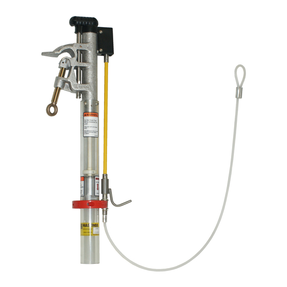
- Page 1 Revision HASTINGS Load Pick Up Tool Manual Model 6600 Model 6605 Operating and Maintenance Manual Manual part number P31086...
- Page 2 H A S T I N G S L O A D P I C K U P T O O L Operating and Maintenance Manual Hastings Fiber Glass Products, Inc. 1301 W. Green St., P.O. Box 218 Hastings, MI 49058 Phone 269-945-9541 •...
-
Page 3: Table Of Contents
Table of Contents Specifications Chapter 1 Basic Operations Chapter 2 Care & Maintenance 7 Chapter 3 Testing Chapter 4 Lower Contact Chapter 5 Trigger Mechanism 10 Chapter 6 Upper Contact Chapter 7 Parts List... -
Page 4: Specifications
Specifications The following specifications apply to the Hastings Model 6600 and Model 6605: Voltage Rating 27kV Nominal, 29.2 kV Maximum* Current Rating 300 Amps* Minimum Conductor Size #6 AWG Maximum Conductor Size 1 ¼” diameter *While the maximum rating for the Model 6600 and Model 6605 is stated above, the actual rating will be based on the lowest rating of any component used with the Load Pickup tool. -
Page 5: Chapter 1 Basic Operations
This manual covers the assembly and operation of both the Model 6600 and Model 6605 load pickup tool. The Model 6600 has the ability to accept a jumper cable ferrule, while the Model 6605 has a stud to accept a jumper clamp. The upper portions of these two tools are identical. - Page 6 Fig. 1 Fig. 2 Fig. 3 The jumper cable should have a tin plated copper threaded ferrule termination on the end to be connected to the load pickup tool. Place the lock washer between the nut and the lower contact assembly and thread the ferrule into the lower contact assembly its full length.
- Page 7 Prior to use Inspect the tool for any damage and for any loose or missing parts. There should be no cracks in the clear tube or any other part of the tool. There should be no visible metal flash or contamination on the inside or outside of the tool.
-
Page 8: Chapter 2 Care & Maintenance
the pull that will be applied to the lanyard during the operation of the tool. Both ends must be securely attached and the de-energized line must have all grounds removed prior to operating the load pickup tool. Tripping Once all of your company’s operating procedures for energizing a line have been completed, the tool can be operated. -
Page 9: Chapter 3 Testing
To include the Load Pickup tool, an additional voltage must be added to the input voltage. An additional voltage of 3.5 is added for model 6600, and 5.0 volts for model 6605. Note that the Load Pickup tool must be in the fired position to complete the... -
Page 10: Chapter 4 Lower Contact
Chapter 4 Lower Contact Disassembly of lower contact The load pickup tool should not be cocked prior to disassembly. Remove screws from red hand guard; pull the hand guard halves apart until holding pins exit the clear tube. (See Fig. 1 &... -
Page 11: Chapter 5 Trigger Mechanism
flat on the ferrule with the setscrew in the bushing holder. Tighten the setscrew and tighten the lock nut on the ferrule. Ferrule model - slide the bushing assembly into the clear tube until the groove in the bushing holder aligns with the mounting holes for the hand guard. Visually check to make sure the pins in the hand guard are in the groove of the contact assembly. -
Page 12: Chapter 6 Upper Contact
Assembly of trigger mechanism Install the 3/32” diameter drive pin through the square bellcrank and the plunger.(“A” in Fig. Grease the small diameter portion of the plunger with lithium grease and insert it into the main body casting. Place the square bellcrank over the two hole lug of the casting and secure it through the top hole of the lug with a 3/16”... - Page 13 Fig. 11 The compression spring inside of the aluminum clamp body can also be removed at this time. To remove the upper bushing, disengage the larger diameter plastic disc by driving out the drive pin with a hammer and a 3/16” punch. If there are any raised deformations around the pinhole, they will have to be removed prior to sliding the upper bushing off that end.
-
Page 14: Chapter 7 Parts List
Fig. 13 Slide the bushing onto the rod until it is beyond the area for the large diameter disc. Make sure that the large internal chamfer is facing the mating chamfer of the small diameter disc. Slide the large diameter disc over the rod and secure in place with the 3/16” diameter drive pin.
Need help?
Do you have a question about the 6605 and is the answer not in the manual?
Questions and answers