Table of Contents
Advertisement
TPower I45 Setup Ma nua l
FCC Information and Copyright
This equipment has been tested and found to comply with the limits of a Class
B digital device, pursuant to Part 15 of the FCC Rules. These limits are designed
to provide reasonable protection against harmful interference in a residential
installation. This equipment generates, uses, and can radiate radio frequency
energy and, if not installed and used in accordance with the instructions, may
cause harmful interference to radio communications. There is no guarantee
that interference will not occur in a particular installation.
The vendor makes no representations or warranties with respect to the
contents here and specially disclaims any implied warranties of merchantability
or fitness for any purpose. Further the vendor reserves the right to revise this
publication and to make changes to the contents here without obligation to
notify any party beforehand.
Duplication of this publication, in part or in whole, is not allowed without first
obtaining the vendor's approval in writing.
The content of this user's manual is subject to be changed without notice and
we will not be responsible for any mistakes found in this user's manual. All the
brand and product names are trademarks of their respective companies.
Advertisement
Table of Contents

Related Manuals for Biostar TPOWER I45


Summary of Contents for Biostar TPOWER I45
- Page 1 TPower I45 Setup Ma nua l FCC Information and Copyright This equipment has been tested and found to comply with the limits of a Class B digital device, pursuant to Part 15 of the FCC Rules. These limits are designed to provide reasonable protection against harmful interference in a residential installation.
-
Page 2: Table Of Contents
Table of Contents Chapter 1: Introduction ............1 Before You Start..................1 Package Checklist ..................1 Motherboard Features................2 Rear Panel Connectors................3 Motherboard Layout................. 4 Chapter 2: Hardware Installation ..........5 Installing Central Processing Unit (CPU) ..........5 FAN Headers....................7 Installing System Memory ................ -
Page 3: Chapter 1: Introduction
TPower I45 CHAPTER 1: INTRODUCTION EFORE TART Thank you for choosing our product. Before you start installing the motherboard, please make sure you follow the instructions below: Prepare a dry and stable working environment with sufficient lighting. Always disconnect the computer from power outlet before operation. -
Page 4: Motherboard Features
Motherboard Manual OTHERBOARD EATURES SPEC LGA 775 Supports Execute Disable Bit / Enhanced Intel Intel Core2Duo / Core2Quad / SpeedStep® / Intel Architecture-64 / Extended Pentium Dual-Core / Celeron Dual-Core / Memory 64 Technology / Virtualization Technology Celeron 4xx processor Support 800 / 1066 / 1333 / 1600 MHz Intel P45 Chipset... -
Page 5: Rear Panel Connectors
Provide Audio-In/Out and microphone connection eSATA Port Connect to SATA devices Board Size 244 (W) x 305 (L) mm Biostar Reserves the right to add or remove support for OS Support Windows 2000 / XP / VISTA any OS with or without notice ANEL... -
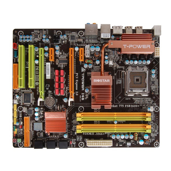
Page 6: Motherboard Layout
Motherboard Manual OTHERBOARD AYOUT JKBMS1 JCFAN1 JATXPWR1 LGA775 CPU1 JUSB2 JUSB1 JUSBV1 JATXPWR2 JNFAN1 JRJ45USB1 Intel JAUDIO1 PEX1_2 JCMOS1 PEX16_1 JPE1 JPE3 JPE5 JPE7 SATA1 JSPDIF_OUT2 Intel ICH10R JPE2 JPE4 JPE6 JPE8 PEX1_1 JCDIN1 SATA2 BAT1 JPE9 PEX16_2 SATA3 CODEC PCI1 Super IDE1... -
Page 7: Chapter 2: Hardware Installation
TPower I45 CHAPTER 2: HARDWARE INSTALLATION (CPU) NSTALLING ENTRAL ROCESSING Special Notice: Remove Pin Cap before installation, and make good preservation for future use. When the CPU is removed, cover the Pin Cap on the empty socket to ensure pin legs won’t be damaged. Pin Cap Step 1: Pull the socket locking lever out from the socket and then raise the lever up to a 90-degree angle. - Page 8 Motherboard Manual Step 2: Look for the triangular cut edge on socket, and the golden dot on CPU should point forwards this triangular cut edge. The CPU will fit only in the correct orientation. Step 2-1: Step 2-2: Step 3: Hold the CPU down firmly, and then lower the lever to locked position to complete the installation.
-
Page 9: Fan Headers
TPower I45 FAN H EADERS These fan headers support cooling-fans built in the computer. The fan cable and connector may be different according to the fan manufacturer. Connect the fan cable to the connector while matching the black wire to pin#1. -
Page 10: Installing System Memory
Motherboard Manual NSTALLING YSTEM EMORY A. Memory Modules Unlock a DIMM slot by pressing the retaining clips outward. Align a DIMM on the slot such that the notch on the DIMM matches the break on the Slot. Insert the DIMM vertically and firmly into the slot until the retaining chip snap back in place and the DIMM is properly seated. - Page 11 TPower I45 B. Memory Capacity DIMM Socket Total Memory DDR2 Module Location Size DDR2_A1 256MB/512MB/1GB/2GB DDR2_A2 256MB/512MB/1GB/2GB Max is 8GB. DDR2_B1 256MB/512MB/1GB/2GB DDR2_B2 256MB/512MB/1GB/2GB C. Dual Channel Memory installation To trigger the Dual Channel function of the motherboard, the memory module must meet the following requirements: Install memory module of the same density in pairs, shown in the following table.
-
Page 12: Connectors And Slots
Motherboard Manual ONNECTORS AND LOTS FDD1: Floppy Disk Connector The motherboard provides a standard floppy disk connector that supports 360K, 720K, 1.2M, 1.44M and 2.88M floppy disk types. This connector supports the provided floppy drive ribbon cables. IDE1: IDE/ATAPI Connector The motherboard has a 32-bit Enhanced PCI IDE Controller that provides PIO Mode 0~4, Bus Master, and Ultra DMA 33/66/100/133 functionality. - Page 13 TPower I45 SATA1~SATA3: Serial ATA Connectors The motherboard has a PCI to SATA Controller with 6 channels SATA interface, it satisfies the SATA 2.0 spec and with transfer rate of 3.0Gb/s. SATA3 SATA2 SATA1 PCI1/PCI2: Peripheral Component Interconnect Slots This motherboard is equipped with 2 standard PCI slots. PCI stands for Peripheral Component Interconnect, and it is a bus standard for expansion cards.
- Page 14 Motherboard Manual PEX16_1: PCI-Express Gen2 x16(x16/CrossFire x8 Speed) Slot PCI-Express 2.0 compliant. Maximum theoretical realized bandwidth of 8GB/s(4GB/s CrossFire) simultaneously per direction, for an aggregate of 16GB/s(8GB/s CrossFire) totally. PEX16_1 slot is reserved for graphics or video cards. The design of this motherboard supports dual PCI-Express graphics cards using CrossFire technology with multiple displays.
-
Page 15: Chapter 3: Headers & Jumpers Setup
TPower I45 CHAPTER 3: HEADERS & JUMPERS SETUP OW TO ETUP UMPERS The illustration shows how to set up jumpers. When the jumper cap is placed on pins, the jumper is “close”, if not, that means the jumper is “open”. Pin opened Pin closed Pin1-2 closed... - Page 16 Motherboard Manual JATXPWR2: ATX Power Source Connector This connector allows user to connect 24-pin power connector on the ATX power supply. Assignment Assignment +3.3V +3.3V -12V +3.3V Ground Ground PS_ON Ground Ground Ground Ground Ground PW_OK Standby Voltage+5V +12V +12V Ground +3.3V JATXPWR1: ATX Power Source Connector...
- Page 17 TPower I45 J1: Auxiliary Power for Graphics This connector is an auxiliary power connection for graphics cards. Exclusive power for the graphics card provides better graphics performance. Assignment +12V Ground Ground JUSB3/JUSB4/JUSB5: Headers for USB 2.0 Ports at Front Panel This header allows user to connect additional USB cable on the PC front panel, and also can be connected with internal USB devices, like USB card reader.
-
Page 18: Cd-Rom Audio-In Connector
Motherboard Manual JAUDIOF1: Front Panel Audio Header This header allows user to connect the front audio output cable with the PC front panel. This header allows only HD audio front panel connector; AC’97 connector is not acceptable. Assignment Mic Left in Ground Mic Right in GPIO... - Page 19 TPower I45 JSPDIF_OUT1/JSPDIF_OUT2: Digital Audio-out Connectors JSPDIF_OUT1 is for connecting the PCI bracket SPDIF output, and JSPDIF_OUT2 is for connecting to the HDMI audio of VGA card. Assignment SPDIF_OUT Ground JSPDIF_OUT2 JSPDIF_OUT1 JSPDIF_IN1: Digital Audio-in Connector This connector allows user to connect the PCI bracket SPDIF input header. Assignment SPDIF_IN Ground...
-
Page 20: Clear Cmos Procedures
Motherboard Manual JCOM1: Serial port Connector The motherboard has a Serial Port Connector for connecting RS-232 Port. Assignment Carrier detect Received data Transmitted data Data terminal ready Signal ground Data set ready Request to send Clear to send Ring indicator JCMOS1: Clear CMOS Header By placing the jumper on pin2-3, it allows user to restore the BIOS safe setting and the CMOS data, please carefully follow the procedures to avoid damaging... - Page 21 TPower I45 JUSBV1/JUSBV2: Power Source Headers for USB Ports Pin 1-2 Close: JUSBV1: +5V for USB ports at JUSB1/JUSB2/JRJ45USB1. JUSBV2: +5V for USB ports at JUSB3/JUSB4/JUSB5. Pin 2-3 Close: JUSBV1: +5V STB for USB ports at JUSB1/JUSB2/ JRJ45USB1. JUSBV2: +5V STB for USB ports at JUSB3/JUSB4/JUSB5. Pin 1-2 close JUSBV1 JUSBV2...
- Page 22 Motherboard Manual BIOS POST Code/CPU Temperature Indicator This indicator will show POST code while booting; after the booting sequence, it will show current CPU temperature. Please refer to Chapter 7.4 for all the BIOS POST codes. JPE1~JPE9: CrossFire Switch Jumpers The setting of these jumpers determines the operation mode of PEX16_1 and PEX16_2.
-
Page 23: Chapter 4: Crossfire Function
TPower I45 CHAPTER 4: CROSSFIRE FUNCTION EQUIREMENTS Only Windows XP/Vista supports CrossFire (Dual Video) function. Two identical CrossFire-ready graphics cards that are ATI certified. The graphics card driver should support CrossFire technology. The power supply unit must provide at least the minimum power required by the system, or the system will be unstable. - Page 24 Motherboard Manual Step 2: Insert the two CrossFire-Ready graphics cards into PEX16_1 (Master) and PEX16_2 (Slave) PEX16_1(Mas ter ) PEX16_2(Slave) Notice: Make sure both the graphics cards are seated into slots completely. Auxiliary Power Step 3: Connect a 4-pin ATX power cable to Connector (J1), this will ensure the stabilization of your system.
-
Page 25: Chapter 5: Raid Functions
TPower I45 CHAPTER 5: RAID FUNCTIONS PERATION YSTEM Supports Windows 2000 Professional, Windows XP, and Windows VISTA. RRAYS RAID supports the following types of RAID arrays: RAID 0: RAID 0 defines a disk striping scheme that improves disk read and write times for many applications. - Page 26 Motherboard Manual RAID 1: Every read and write is actually carried out in parallel across 2 disk drives in a RAID 1 array system. The mirrored (backup) copy of the data can reside on the same disk or on a second redundant drive in the array.
- Page 27 TPower I45 RAID 1+0 (For Onboard SATA Only): RAID 1 drives can be stripped using RAID 0 techniques. Resulting in a RAID 1+0 solution for improved resiliency, performance and rebuild performance. Features and Benefits Drives: Minimum 4, and maximum is 6 or 8, depending on the platform. ...
- Page 28 Motherboard Manual RAID 5 (For Onboard SATA Only): RAID 5 stripes both data and parity information across three or more drives. It writes data and parity blocks across all the drives in the array. Fault tolerance is maintained by ensuring that the parity information for any given block of data is placed on a different drive from those used to store the data itself.
-
Page 29: Chapter 6: T-Power Bios & Software
TPower I45 CHAPTER 6: T-POWER BIOS & SOFTWARE BIOS OWER T-Power BIOS Features Overclocking Navigator Engine (O.N.E.) Memory Integration Test (M.I.T., under Overclock Navigator Engine) BIO-Flasher: Update BIOS file from USB Flash Drive or FDD Self Recovery System (S.R.S) Smart Fan Function CMOS Reloading Program !! WARNING !! For better system performance, the BIOS firmware is being... - Page 30 Motherboard Manual Manual Overclock System (M.O.S.) MOS is designed for experienced overclock users. It allows users to customize personal overclock settings. BIOS SETUP UTILITY Main Advanced PCIPnP Boot Chipset O.N.E Exit Over-Clocking Navigator setting Options WARNING: Setting wrong values in below sections Normal may cause system to malfunction.
-
Page 31: Dram Frequency
TPower I45 FSB(Bsel) To NorthBridge Latch This item allows you to select the FSB Frequency. DRAM Frequency To get better system performance, sometimes downgrading the memory frequency is necessary when CPU frequency is adjusted over the upper limit. DDR2 Enhanced Mode This item allows you to control the DDR2 ram enhanced mode. - Page 32 Motherboard Manual V6 Tech Engine This engine will make a good over-clock performance. BIOS SETUP UTILITY Main Advanced PCIPnP Boot Chipset O.N.E Exit Over-Clocking Navigator setting Options WARNING: Setting wrong values in below sections V6-Tech Engine may cause system to malfunction. V8-Tech Engine Over-Clocking Navigator [Automate OverClock]...
- Page 33 TPower I45 Notices: Not all types of Intel CPU perform above overclock setting ideally; the difference will be based on the selected CPU model. B. Memory Integration Test (M.I.T.) This function is under “Overclocking Navigator Engine” item. MIT allows users to test memory compatibilities, and no extra devices or software are needed.
- Page 34 Motherboard Manual C. BIO-Flasher BIO-Flasher is a BIOS flashing utility providing you an easy and simple way to update your BIOS via USB pen drive or floppy disk. The BIO-Flasher is built in the BIOS chip. To enter the utility, press <F12> during the Power-On Self Tests (POST) procedure while booting up.
- Page 35 TPower I45 D. Self Recovery System (S.R.S.) This function can’t be seen under BIOS setup; and is always on whenever the system starts up. However, it can prevent system hang-up due to inappropriate overclock actions. When the system hangs up, S.R.S. will automatically log in the default BIOS setting, and all overclock settings will be re-configured.
- Page 36 Motherboard Manual Smart Fan Calibration Choose this item and then the BIOS will automatically test and detect the CPU/System fan functions and show CPU/System fan speed. Fan Ctrl OFF(℃) If the CPU/System temperature is lower than the set value, the CPU/ System fan will turn off.
-
Page 37: T-Power Software
TPower I45 OWER OFTWARE T-Power2 is an integration of four functions: OC Tweaker for over-clock, eHot-Line for technical support, BIOS-watch for system monitor, and Biostar Flash for BIOS update. Installing T-Power2 1. Insert the Setup CD to the optical drive. - Page 38 On the main panel, you can click on the OC Tweaker button to launch this function. The OC Tweaker provides automatic/manual over-clock function for BIOSTAR motherboard, and even for some BIOSTAR VGA card (VR8xxx series only) which is powered by V-Ranger. Th is a rea shows clo ck...
- Page 39 TPower I45 <Auto Over-clock> By this function, the utility will set the best and stable performance and frequency automatically. Click on then a Warning dialog will show. This dialog tells that all running applications should be closed before the auto over-clock procedure.
- Page 40 Motherboard Manual <V3/V6/V9/V12/V15 Engine> E X: This means V9 engine is acti vated. By clicking the utility would over-clock the system with certain fixed percentage. When the V3/V6/V9/V12/V15 engine is activated, you will see the green light bar on the left rising to the top of the button.
- Page 41 TPower I45 BIO-watch BIO-watch is a control and monitor utility that helps you to maintain the health of the PC. It provides real-time information of CPU/GPU/System temperature, fan speed, and voltage; and fan control function. Th is area sh ows rea l-time i nformation of tempe ratu re/fan speed/vo ltage Cu rrent fan speed Cu rrent CPU/GPU/System tempera tu re...
- Page 42 Motherboard Manual Increase Speed Auto-Control Decrease Speed Click the auto-control off and then the adjust level will show; use the level to increase/decrease the fan speed. Be aware if the fan level been down to 0%, the fan will still not completely stop; this is for your system’s protection. <Fan Control Settings>...
- Page 43 TPower I45 eHot-Line eHot-Line is a convenient utility that helps you to contact with our Tech-Support system. This utility will collect the system information which is useful for analyzing the problem you may have encountered, and then send these information to our tech-support department to help you fix the problem. Before you use this utility, please set Outlook Express as your default e-mail client application program.
- Page 44 If you are not using Outlook Express as your default e-mail client application, you may need to save the system information to a .txt file and send the file to our tech support with other e-mail application. Go to the following web http://www.biostar.com.tw/app/en-us/about/contact.php for getting our contact information.
- Page 45 TPower I45 Biostar Flash Biostar Flash is a convenient utility which allows you to update your motherboard BIOS under Windows system. Shows curr ent BIOS infor mati on Restart Your System (AMI BIOS) Clear CMOS function (Award BIOS) Update BIOS...
- Page 46 Motherboard Manual <Update BIOS> Before doing this, please download the proper BIOS file from our website: www.biostar.com.tw Update BIOS procedure should be run with Clear CMOS (or Restart) function, so please check on Clear CMOS (or Restart) first. (Restart Your System)
-
Page 47: Chapter 7: Useful Help
TPower I45 CHAPTER 7: USEFUL HELP RIVER NSTALLATION After you installed your operating system, please insert the Fully Setup Driver CD into your optical drive and install the driver for better system performance. You will see the following window after you insert the CD The setup guide will auto detect your motherboard and operating system. -
Page 48: Extra Information
Motherboard Manual XTRA NFORMATION CPU Overheated If the system shutdown automatically after power on system for seconds, that means the CPU protection function has been activated. When the CPU is over heated, the motherboard will shutdown automatically to avoid a damage of the CPU, and the system may not power on again. -
Page 49: Ami Bios Beep Code
TPower I45 AMI BIOS B Boot Block Beep Codes Number of Beeps Description No media present. (Insert diskette in floppy drive A:) “AMIBOOT.ROM” file not found in root directory of diskette in Insert next diskette if multiple diskettes are used for recovery Flash Programming successful File read error No Flash EPROM detected... -
Page 50: Ami Bios Post Code
Motherboard Manual AMI BIOS P Checkpoint Description Disable NMI, Parity, video for EGA, and DMA controllers. Initialize BIOS, POST, Runtime data area. Also initialize BIOS modules on POST entry and GPNV area. Initialized CMOS as mentioned in the Kernel Variable "wCMOSFlags."... - Page 51 TPower I45 Checkpoint Description Displaying sign-on message, CPU information, setup key message, and any OEM specific information. Initializes different devices through DIM. See DIM Code Checkpoints section of document for more information. USB controllers are initialized at this point. Initializes DMAC-1 & DMAC-2. Initialize RTC date/time.
-
Page 52: Troubleshooting
Motherboard Manual ROUBLESHOOTING Probable Solution No power to the system at all Make sure power cable is Power light don’t illuminate, fan securely plugged in. inside power supply does not turn Replace cable. Contact technical support. Indicator light on keyboard does not turn on. - Page 53 TPower I45 This page is intentionally left blank.
-
Page 54: Appendencies: Spec In Other Language
Motherboard Manual APPENDENCIES: SPEC IN OTHER LANGUAGE ERMAN Spezifikationen LGA 775 Unterstützt Execute Disable Bit / Enhanced Intel Intel Intel Core2Duo / Core2Quad / SpeedStep® / Intel Architecture-64 / Extended Pentium Dual-Core / Celeron Dual-Core / Memory 64 Technology / Virtualization Technology Celeron 4xx Prozessoren 800 / 1066 / 1333 / 1600 MHz Intel P45... - Page 55 PS/2-Maus Rückseiten-E LAN-Anschluss USB-Anschluss Audioanschluss eSATA Anschluss Platinengröße 244 mm (B) X 305 mm (L) Biostar behält sich das Recht vor, ohne Ankündigung OS-Unterstüt Windows 2000 / XP / VISTA die Unterstützung für ein Betriebssystem zung hinzuzufügen oder zu entfernen.
-
Page 56: France
Motherboard Manual RANCE SPEC LGA 775 Prend en charge les technologies d'exécution de bit de Processeurs Intel Core2Duo / Core2Quad désactivation / Intel SpeedStep® optimisée/ / Pentium Dual-Core / Celeron Dual-Core / d'architecture Intel 64 / de mémoire étendue 64 / de Celeron 4xx virtualisation Bus frontal 800 / 1066 / 1333 / 1600 MHz... - Page 57 Fiche audio Port eSATA Dimensions 244 mm (l) X 305 mm (H) de la carte Biostar se réserve le droit d'ajouter ou de supprimer le Support SE Windows 2000 / XP / VISTA support de SE avec ou sans préavis.
-
Page 58: Italian
Motherboard Manual TALIAN SPECIFICA LGA 775 Supporto di Execute Disable Bit / Enhanced Processore Intel Core2Duo / Core2Quad Intel SpeedStep® / Architettura Intel 64 / / Pentium Dual-Core / Tecnologia Extended Memory 64 / Tecnologia Celeron Dual-Core / Celeron 4xx Virtualization 800 / 1066 / 1333 / 1600 MHz Intel P45... - Page 59 Connettore audio Porta eSATA Dimension 244 mm (larghezza) x 305 mm i scheda (altezza) Sistemi Biostar si riserva il diritto di aggiungere o operativi Windows 2000 / XP / VISTA rimuovere il supporto di qualsiasi sistema supportati operativo senza preavviso.
-
Page 60: Spanish
Motherboard Manual PANISH Especificación LGA 775 Admite Bit de deshabilitación de ejecución / Intel Procesador Intel Core2Duo / Core2Quad / SpeedStep® Mejorado / Intel Architecture-64 / Pentium Dual-Core / Celeron Dual-Core / Tecnología Extended Memory 64 / Tecnología de Celeron 4xx virtualización 800 / 1066 / 1333 / 1600 MHz Conjunto de... - Page 61 Tamaño de 244 mm. (A) X 305 Mm. (H) la placa Soporte de Biostar se reserva el derecho de añadir o retirar el sistema Windows 2000 / XP / VISTA soporte de cualquier SO con o sin aviso previo. operativo...
-
Page 62: Portuguese
Motherboard Manual ORTUGUESE ESPECIFICAÇÕES LGA 775 Suporta as tecnologias Execute Disable Bit / Enhanced Processador Intel Core2Duo / Core2Quad Intel SpeedStep® / Intel Arquitecture -64 / Extended / Pentium Dual-Core / Celeron Dual-Core / Memory 64 / Virtualization Celeron 4xx 800 / 1066 / 1333 / 1600 MHz Intel P45 Chipset... - Page 63 Porta eSATA Tamanho 244 mm (L) X 305 mm (A) da placa Sistemas A Biostar reserva-se o direito de adicionar ou remover operativos Windows 2000 / XP / VISTA suporte para qualquer sistema operativo com ou sem suportados aviso prévio.
-
Page 64: Polish
Motherboard Manual OLISH SPEC LGA 775 Obsługa Execute Disable Bit / Enhanced Intel Procesor Intel Core2Duo / Core2Quad / Procesor SpeedStep® / Intel Architecture-64 / Extended Pentium Dual-Core / Celeron Dual-Core / Memory 64 Technology / Virtualization Technology Celeron 4xx 800 / 1066 / 1333 / 1600 MHz Intel P45 Chipset... - Page 65 Back Panel Port LAN Port USB Gniazdo audio Port eSATA Wymiary 244 mm (S) X 305 mm (W) płyty Obsluga Biostar zastrzega sobie prawo dodawania lub systemu Windows 2000 / XP / VISTA odwoływania obsługi dowolnego systemu operacyjne operacyjnego bez powiadomienia.
-
Page 66: Russian
Motherboard Manual USSIAN СПЕЦ LGA 775 Поддержка технологий Execute Disable Bit / (центральн Процессор Intel Core2Duo / Core2Quad / Enhanced Intel SpeedStep® / Intel Architecture-64 ый Pentium Dual-Core / Celeron Dual-Core / / Extended Memory 64 Technology / технологии процессор) Celeron 4xx виртуализация... - Page 67 Гнездо для подключения ода наушников eSATA порт Размер 244 мм (Ш) X 305 мм (В) панели Biostar сохраняет за собой право добавлять или Поддержка Windows 2000 / XP / VISTA удалять средства обеспечения для OS с или без предварительного уведомления.
-
Page 68: Arabic
Motherboard Manual RABIC اﻟﻤﻮاﺻﻔﺎت ﺗﺪﻋﻢ ﺗﻘﻨﻴﺎتExecute Disable Bit / Enhanced Intel LGA 775 SpeedStep® / Intel Architecture-64 / Extended ﻣﻌﺎﻟﺠﺎتIntel Core2Duo / Core2Quad / اﻟﻤﻌﺎﻟﺠﺔ وﺣﺪة Memory 64 Technology / Virtualization Pentium Dual-Core / Celeron Dual-Core / یﺔ اﻟﻤﺮآﺰ Technology Celeron 4xx ﺼﻞ... -
Page 69: Smart Fan
ﻋﺪد ﻣﻨﺎﻓﺬ اﻝﺨﻠﻔﻴﺔ اﻝﻠﻮﺡﺔ ﻋﺪد ﻣﻘﺒﺲ ﺹﻮت ﻋﺪد eSATA ﻣﻨﻔﺬ ﺎع ارﺗﻔ ﻣﻢ ﻋﺮض ﻣﻢ اﻝﻠﻮﺡﺔ ﺡﺠﻢ ﺕﺤﺘﻔﻆBiostar ﺏﺈﺧﻄﺎر ﺕﺸﻐﻴﻞ ﻥﻈﺎم ﻷي اﻝﺪﻋﻢ إزاﻝﺔ أو إﺿﺎﻓﺔ ﻓﻲ ﺏﺤﻘﻬﺎ Windows 2000 / XP / VISTA اﻝﺘﺸﻐﻴﻞ أﻥﻈﻤﺔ دﻋﻢ إﺧﻄﺎر ﺏﺪون... -
Page 70: Japanese
Motherboard Manual APANESE 仕様 LGA 775 Execute Disable Bit / Enhanced Intel SpeedStep® / Intel Core2Duo / Core2Quad / Intel Architecture-64 / Extended Memory 64 Pentium Dual-Core / Celeron Dual-Core / Technology / Virtualization Technologyをサポートします Celeron 4xx processor 800 / 1066 / 1333 / 1600 MHz Intel P45 チップセット... - Page 71 オンボードコ S/PDIFインコネクタ デジタルオーディオイン機能をサポートします ネクタ CPUファンヘッダ CPUファン電源装置(スマートファン機能を搭載) システムファンヘッダ システムファン電源装置 CMOSクリアヘッダ 各コネクタは2つのフロントパネルUSBポートをサポートし USBコネクタ ます 電源コネクタ(24ピン) 電源コネクタ(8ピン) 電源コネクタ(4ピン) PS/2キーボード PS/2マウス LANポート 背面パネル USBポート オーディオジャック eSATAポート ボードサイズ 244 mm (幅) X 305 mm (高さ) Biostarは事前のサポートなしにOSサポートを追加または削 OSサポート Windows 2000 / XP / VISTA 除する権利を留保します。 2008/04/23...
Need help?
Do you have a question about the TPOWER I45 and is the answer not in the manual?
Questions and answers