Table of Contents
Advertisement
Quick Links
I945P-A7
FCC Information and Copyright
This equipment has been tested and found to comply with the limits of a Class
B digital device, pursuant to Part 15 of the FCC Rules. These limits are designed
to provide reasonable protection against harmful interference in a residential
installation. This equipment generates, uses and can radiate radio frequency
energy and, if not installed and used in accordance with the instructions, may
cause harmful interference to radio communications. There is no guarantee
that interference will not occur in a particular installation.
The vendor makes no representations or warranties with respect to the
contents here and specially disclaims any implied warranties of merchantability
or fitness for any purpose. Further the vendor reserves the right to revise this
publication and to make changes to the contents here without obligation to
notify any party beforehand.
Duplication of this publication, in part or in whole, is not allowed without first
obtaining the vendor's approval in writing.
The content of this user's manual is subject to be changed without notice and
we will not be responsible for any mistakes found in this user's manual. All the
brand and product names are trademarks of their respective companies.
i
Advertisement
Table of Contents

Related Manuals for Biostar I945P-A7


Summary of Contents for Biostar I945P-A7
- Page 1 I945P-A7 FCC Information and Copyright This equipment has been tested and found to comply with the limits of a Class B digital device, pursuant to Part 15 of the FCC Rules. These limits are designed to provide reasonable protection against harmful interference in a residential installation.
-
Page 2: Table Of Contents
Table of Contents Chapter 1: Introduction ... 1 Motherboard Features ... 1 Package Checklist ... 6 Layout and Components ... 7 Chapter 2: Hardware Installation ... 8 Installing Central Processing Unit (CPU) ... 8 FAN Headers ... 10 Installing System Memory ... 11 Connectors and Slots ... -
Page 3: Chapter 1: Introduction
Super I/O Chip: ITE IT8712F. Low Pin Count Interface. Provides the most commonly used legacy Super I/O functionality. Environment Control initiatives, H/W Monitor Fan Speed Controller ITE's "Smart Guardian" function I945P-A7 EATURES Intel ICH7 (for Rev 2.0). -
Page 4: Gigabit Lan
I945P-A7 System Memory Supports dual channel DDR2 up to 8 banks. Supports DDR2 533 (266MHz) / 667 (333MHz) for a theoretical maximum bandwidth of 10.7 GB/s. Supports 256-Mb, 512-Mb, or 1G-Mb DDR technologies for x8 and x16 devices. Supports non-ECC DIMMs. - Page 5 I945P-A7 Serial ATA Controller integrated in ICH7R. Supports Serial ATA 2.0 specification. Data transfer rate up to 3GB/s. Supports 4 Serial ATA (SATA) devices. Intel Advanced Host Controller (AHCI). Integrated RAID 0,RAID 1, and RAID 0+1 capabilities (only for Rev 1.0).
-
Page 6: Back Panel I/O Connectors
I945P-A7 Internal On-board I/O Connectors and Headers 1 IDE connector supports 2 hard disk devices. 1 front panel header supports front panel facilities. 1 CD-in connector supports 1 CD-ROM audio-in device. 1 front audio header supports front panel audio-out function. - Page 7 I945P-A7 6 audio ports support 8+2 channels audio-out facilities. (ALC882). PS/2 Mouse Parallel COM1 PS/2 Keyboard Center/Left Rear Side Notice for ALC882 Codec: When connecting audio devices into audio ports, the audio driver will auto-detect and pop-up the port function selection window. User can choose different functions for each port according to personal preference.
-
Page 8: Bios & Software
Rear I/O Panel for ATX Case X 1 USB 2.0 Cable X1 (optional) S/PDIF Cable X 1 (optional) IEEE 1394 Cable X 1 (optional) Retention Bracket X 1 (optional) Serial ATA Power Switch Cable X 1 (optional) Dual Video Bridge (BRI-2) Connector X 1 (optional) I945P-A7... -
Page 9: Layout And Components
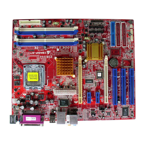
PCI-Ex16 JSPDIF_IN1 PCI-Ex1_1 (for v1.0) (optional) JSPDIF_OUT1 PCI-Ex1_2 (for v1.0) JCDIN1 PCI-EX Codec PCI1 PCI2 Giga PCI3 Note: ■ represents the 1 I945P-A7 LGA775 CPU1 Intel 945P Intel ICH7R (v1.0) ICH7(v2.0) BIOS BAT1 IEEE1394 J1394PWR1 Chip (optional) (optional) J1394A1 (optional) pin. -
Page 10: Chapter 2: Hardware Installation
I945P-A7 CHAPTER 2: HARDWARE INSTALLATION (CPU) NSTALLING ENTRAL ROCESSING Codec CPU1 Special Notice: Remove Pin Cap before installation, and make good preservation for future use. When the CPU is removed, cover the Pin Cap on the empty socket to ensure pin legs won’t be damaged. - Page 11 I945P-A7 Step 2: Look for the black cut edge on socket, and the white dot on CPU should point forwards this black cut edge. The CPU will fit only in the correct orientation. Step 2-1: Step 2-2: Step 3: Hold the CPU down firmly, and then close the lever to complete the installation.
-
Page 12: Fan Headers
The JCFAN1 supports system cooling fan with Smart Fan Control utility. It supports 4-pin head connector. When connecting with wires onto connectors, please note that the red wire is the positive and should be connected to pin#2, and the black wire is Ground and should be connected to GND. I945P-A7 JCFAN1 JSFAN2 Assignment... -
Page 13: Installing System Memory
DIMM on the slot such that the notch on the DIMM matches the break on the Slot. Insert the DIMM vertically and firmly into the slot until the retaining chip snap back in place and the DIMM is properly seated. I945P-A7 EMORY... -
Page 14: Connectors And Slots
This connector supports the provided floppy drive ribbon cables. Codec IDE1: Hard Disk Connector (IDE2 and IDE3 are optional.) The motherboard has a 32-bit Enhanced PCI IDE Controller that provides PIO Mode 0~4, Bus Master, and Ultra DMA 33/66/100 functionality. - Page 15 I945P-A7 PCI-Ex16: PCI-Express x16 Slot PCI-Express 1.0a compliant. Maximum theoretical realized bandwidth of 4GB/s simultaneously per direction, for an aggregate of 8GB/s totally. PCI-Ex1_1/PCI-Ex1_2: PCI-Express x1 slots PCI-Express 1.0a compliant. Data transfer bandwidth up to 250MB/s per direction; 500MB/s in total.
- Page 16 I945P-A7 PCI1~PCI3: Peripheral Component Interconnect Slots This motherboard is equipped with 3 standard PCI slots. PCI stands for Peripheral Component Interconnect, and it is a bus standard for expansion cards. This PCI slot is designated as 32 bits. Codec PCI1...
-
Page 17: Chapter 3: Headers & Jumpers Setup
“close”, if not, that means the jumper is “open”. Pin opened ETAIL ETTINGS JATXPWR1: ATX Power Connector This connector allows user to connect 24-pin power connector on the ATX power supply. Codec I945P-A7 Pin closed Pin1-2 closed Assignment +3.3V +3.3V Ground Ground Ground... - Page 18 I945P-A7 JATXPWR2: ATX Power Connector By connecting this connector, it will provide +12V to CPU power circuit. Codec JSPDIF_OUT1: Digital Audio-out Connector This connector allows user to connect the PCI bracket SPDIF output header. Codec JSPDIF_IN1 (optional): Digital Audio-in Connector This connector allows user to connect the PCI bracket SPDIF input header.
- Page 19 I945P-A7 J1394A1 (optional): Header for 1394 Firewire Port at Front Panel Codec J1394PWR1 (optional): Power Source for 1394 Firewire Port This header allows user to connect the digital image device, like DV, D8, or V8, etc. Codec JCDIN1: CD-ROM Audio-in Connector This connector allows user to connect the audio source from the variety devices, like CD-ROM, DVD-ROM, PCI sound card, PCI TV turner card etc..
- Page 20 I945P-A7 Right channel input...
- Page 21 I945P-A7 JAUDIOF1: Front Panel Audio Header This header allows user to connect the front audio output cable with the PC front panel. It will disable the output on back panel audio connectors. With High Definition Audio Codec: ALC882 Codec With AC’97 Sound Codec: ALC655 (optional)
- Page 22 Pin 2-3. JUSB3/JUSB4: Front USB Headers This motherboard provides 2 USB 2.0 headers, which allows user to connect additional USB cable on the PC front panel, and also can be connected with internal USB devices, like USB card reader.
- Page 23 I945P-A7 SATA1~SATA4: Serial ATA Connectors The motherboard has a PCI to SATA Controller with 4 channels SATA interface, it satisfies the SATA 2.0 spec and with transfer rate of 3Gb/s. Codec JPANEL1: Front Panel Header This 24-pin connector includes Power-on, Reset, HDD LED, Power LED, Sleep button, speaker and IrDA Connection.
- Page 24 I945P-A7 JCMOS1: Clear CMOS Header By placing the jumper on pin2-3, it allows user to restore the BIOS safe setting and the CMOS data, please carefully follow the procedures to avoid damaging the motherboard. Codec ※ Clear CMOS Procedures: Remove AC power line.
-
Page 25: Chapter 4: Useful Help
BIOS contents are corrupted. In this Case, please follow the procedure below to restore the BIOS: Make a bootable floppy disk. Download the Flash Utility “AWDFLASH.exe” from the Biostar website: www.biostar.com.tw Confirm motherboard model and download the respectively BIOS from Biostar website. -
Page 26: Cpu Overheated
If the system shutdown automatically after power on system for seconds, that means the CPU protection function has been activated. When the CPU is over heated, the motherboard will shutdown automatically to avoid a damage of the CPU, and the system may not power on again. -
Page 27: Troubleshooting
Screen message says “Invalid Configuration” or “CMOS Failure.” Cannot boot system after installing second hard drive. I945P-A7 Solution Make sure power cable is securely plugged in. Replace cable. Contact technical support. -
Page 28: Chapter 5: Dual Video Function
Make sure both the graphics cards are seated into slots completely. PCI-Ex1_1 and PCI-Ex1_2 slots are only for Rev 1.0. Step 4: Insert the Dual Video Bridge (BRI-2) connector on the gold-fingers on each graphics card. I945P-A7 ARDS PCI-Ex16 PCI-EX... -
Page 29: Things To Notice
Dual Video Mode: Use Dual Video Bridge (BRI-2) connector to link two identical PCI-E x16 interface graphics cards that are NVIDIA certified. Coordinate with graphics card driver to set Dual Video function. I945P-A7 Side view Gold-fingers on two graphics... -
Page 30: Chapter 6: Warpspeeder
YSTEM EQUIREMENT OS Support: Windows 98 SE, Windows Me, Windows 2000, Windows XP DirectX: DirectX 8.1 or above. (The Windows XP operating system includes DirectX 8.1. If you use Windows XP, you do not need to install DirectX 8.1.) I945P-A7... -
Page 31: Installation
Tray Icon utility and [WarpSpeeder™] utility will be automatically and immediately launched after you click “Finish” button. Usage: The following figures are just only for reference, the screen printed in this user manual will change according to your motherboard on hand. I945P-A7... -
Page 32: Warpspeeder™] Includes 1 Tray Icon And 5 Panels
I945P-A7 ™] PEEDER INCLUDES TRAY ICON AND PANELS 1. Tray Icon: Whenever the Tray Icon utility is launched, it will display a little tray icon on the right side of Windows Taskbar. This utility is responsible for conveniently invoking [WarpSpeeder™] Utility. -
Page 33: Main Panel
I945P-A7 2. Main Panel If you click the tray icon, [WarpSpeeder™] utility will be invoked. Please refer to the following figure; the utility’s first window you will see is Main Panel. Main Panel contains features as follows: a. Display the CPU Speed, CPU external clock, Memory clock, AGP clock, and PCI clock information. - Page 34 I945P-A7 3. Voltage Panel Click the Voltage button in Main Panel, the button will be highlighted and the Voltage Panel will slide out to up as the following figure. In this panel, you can decide to increase CPU core voltage and Memory voltage or not.
- Page 35 I945P-A7 4. Overclock Panel Click the Overclock button in Main Panel, the button will be highlighted and the Overclock Panel will slide out to left as the following figure. Overclock Panel contains the these features: a. “–3MHz button”, “-1MHz button”, “+1MHz button”, and “+3MHz button”: provide user the ability to do real-time overclock adjustment.
- Page 36 I945P-A7 “Auto-overclock button”: User can click this button and [WarpSpeeder™] will set the best and stable performance and frequency automatically. [WarpSpeeder™] utility will execute a series of testing until system fail. Then system will do fail-safe reboot by using Watchdog function. After reboot, the [WarpSpeeder™] utility will restore to the hardware default...
-
Page 37: About Panel
I945P-A7 6. About Panel Click the “about” button in Main Panel, the button will be highlighted and the About Panel will slide out to up as the following figure. In this panel, you can get model name and detail information in hints of all the chipset that are related to overclocking. - Page 38 I945P-A7 Note: Because the overclock, overvoltage, and hardware monitor features are controlled by several separate chipset, [WarpSpeeder™] divide these features to separate panels. If one chipset is not on board, the correlative button in Main panel will be disabled, but will not interfere other panels’...
Need help?
Do you have a question about the I945P-A7 and is the answer not in the manual?
Questions and answers