Table of Contents
Advertisement
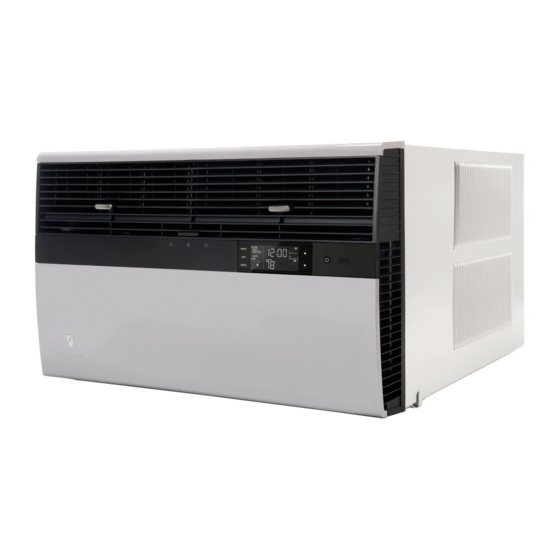
Room Air Conditioners
Standard Chassis Models
Kühl
Kühl +
Electric Heat
Kühl +
Heat Pump
1
93001403_04
115-Volt:
KCS08A10A, KCS10A10A, KCS12A10A, KCS14A10A, KCM14A10A
KCS12A30A, KCS16A30A, KCM18A30A, KCM21A30A KCL24A30A,
230-Volt:
KCL24A30B, KCL28A30A, KCL36A30A
230-Volt:
KES12A33A, KES16A33A, KEM18A34A, KEL24A35A,
KEL24A35B, KEL36A35A
115-Volt:
KHS10A10A
KHM12A33A, KHM18A34A, KHL24A35A
230-Volt:
Advertisement
Table of Contents
Troubleshooting

Related Manuals for Friedrich KHL24A35A


Summarization of Contents
Introduction and Safety
Important Safety Information
Essential safety warnings and precautions for handling the unit.
New Kühl Control Features
Overview of advanced control options and programming for Kühl models.
Specifications
Performance and Electrical Data
Detailed refrigeration performance data and electrical ratings for all models.
Electrical Data and Wiring Requirements
Information on circuit ratings, breaker/plug types, and wiring.
Operation and User Interface
User Interface and Control Panel
Guide to the unit's control panel, display, and button functions.
Unit Modes and Functions
Explanation of cooling, heating, fan modes, and operational sequences.
Remote Control Usage
Instructions for operating the air conditioner using the remote control.
Maintenance and Installation
Routine Maintenance Procedures
Steps for cleaning coils, filters, and general unit upkeep.
Chassis Removal and Installation
Procedures for safely removing and installing the unit chassis.
Troubleshooting and Diagnostics
Diagnostic Codes and Troubleshooting Tips
Table of diagnostic codes and corresponding control board actions.
Refrigerant System Diagnosis
Flowcharts for diagnosing heating and cooling cycle refrigerant issues.
Component Testing and Repair
Compressor Testing and Checks
Methods for testing compressor voltage, amperage, and resistance.
Reversing Valve Testing
Description of the reversing valve and procedures for testing its function.
R-410A Sealed System Repairs
Procedures for repairing R-410A systems, including charging and compressor replacement.
Wiring Diagrams
Model-Specific Wiring Diagrams
Electrical diagrams illustrating connections for various unit models.
Appendix, Warranty, and Support
Appendix: Thermistor Values
Table of thermistor resistance values at different temperatures for diagnostics.
Limited Warranty and Support Information
Details on warranty coverage, limitations, and technical support contacts.
Need help?
Do you have a question about the KHL24A35A and is the answer not in the manual?
Questions and answers