Table of Contents
Advertisement
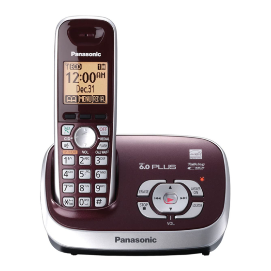
Telephone Equipment
KX-TG6572C
Model No.
KX-TG6572R
KX-TGA653C
KX-TGA653R
Expandable Digital Cordless Answering
System
C: Dark Blue Metallic Version
R: Wine Red Version
(for U.S.A)
© Panasonic System Networks Co., Ltd. 2010
Unauthorized copying and distribution is a violation
of law.
ORDER NO. KM41009258CE
F13
Advertisement
Table of Contents

Related Manuals for Panasonic KX-TG6572R


Summarization of Contents
Safety and Warning Information
General Service Warning
Manual for experienced technicians; improper repair risks injury or death.
Critical Safety Components
Safety-critical parts are marked; use only specified manufacturer parts.
Lead-Free Soldering Precautions
Guidance on lead-free solder properties and handling precautions.
Safety Precautions and Procedures
For Service Technicians
Guidelines for repair service to prevent fires, injury, or electric shock.
Battery Caution and Handling
Warning on battery replacement risks and proper disposal methods.
Product Specifications
DECT 6.0 Standards and RF
Details DECT 6.0, channels, frequency, modulation, and RF power.
Power, Dimensions, and Weight
Specs for power sources, consumption, dimensions, and mass of device units.
Technical Descriptions
US-DECT System Overview
Explanation of the US-DECT frequency range and its usage.
TDMA Frame and Handset Linking
Details on TDMA system, frame format, and handset linking.
Signal Flow in Radio Parts
Reception and Transmission Signal Paths
Describes signal processing for reception and transmission in radio parts.
Base Unit Main Block Diagram
Base Unit Component Connections
Schematic overview of the main components and connections of the base unit.
Base Unit RF Part Block Diagram
RF Component Connections
Diagram illustrating the RF components and their connections for the base unit.
Base Unit Circuit Operation
BBIC, Flash Memory, and EEPROM Functions
Details BBIC, Flash Memory, and EEPROM functions and data storage.
Power Supply and Reset Circuits
Base Unit Power Supply and Reset Operation
Operation of voltage conversion and reset signals for the base unit.
Charge Circuit Operation
Charger Unit Charge Circuit
Schematic of the charge circuit supplied by the AC adaptor.
Telephone Line Interface
Bell Signal and Off Hook Circuit Operation
How bell signals are detected and off-hook conditions are managed.
Pulse Dial and Side Tone Circuits
Operation of pulse dialing and side tone cancellation circuits.
Parallel Connection Detection Circuit
Auto Disconnect Circuit Function
Circuit to determine parallel phone usage and disconnect automatically.
Caller ID and Call Waiting Caller ID
Caller ID Message Formats
Describes FSK modulated data formats for caller ID information.
Call Waiting Caller ID Format
CAS and ACK Signal Flow
Explains signal flow for CAS and ACK signals in call waiting.
Handset Block Diagrams
Handset Main Block Diagram
Overview of ICs and connections within the handset.
Handset RF Part Block Diagram
Handset RF Component Connections
Diagram of RF components and their interconnections for the handset.
Handset Circuit Operation
Handset Power Supply and ICs
Details handset ICs and the power supply/reset circuit operation.
Handset Charging and Battery Detection
Handset Battery Charging Process
Operation of charge current control for the handset battery.
Battery Low and Power Down Detection
How BBIC detects low battery and initiates power down.
Charger Unit Circuit Operation
Charger Control via Handset
Explains how the charger operation is controlled by the handset.
Signal Route Information
Handset and Base Unit Signal Paths
Details signal paths for handset, base unit, ICM, Caller ID, and Bell Detection.
RF Part Signal Route
Handset and Base Unit RF Signal Paths
Outlines signal routes for handset and base unit RF transmission and reception.
Location, Installation, and Operation Instructions
Location of Controls and Components
Refer to Operating Instructions for location of controls and components.
Installation and Operating Instructions
Instructions for installation and operation are available in the Operating Instructions.
Test Mode - Engineering Mode
Base Unit Engineering Mode Procedure
Step-by-step guide to enter and use Engineering Mode on the base unit.
Handset Engineering Mode
Handset Engineering Mode Procedure
Procedures for accessing and operating Engineering Mode on the handset.
Service Mode - Clearing User Settings
Handset User Setting Initialization
How to reset user settings on the handset to factory defaults.
Troubleshooting Guide
Troubleshooting Flowchart
A flowchart to diagnose and resolve common issues with the phone system.
Power Check Procedures
Base Unit and Handset Power Checks
Steps to verify power supply and related circuits in base unit and handset.
Record Check Procedures
Base Unit Message Recording Check
Steps to troubleshoot issues with recording incoming messages on the base unit.
Auto Disconnect Activation Time Adjustment
Adjusting Auto Disconnect Settings
How to adjust auto disconnect settings for different line conditions.
Link Confirmation Procedures
Base Unit and Handset Link Checks
Steps to verify the link between base unit and handset.
RF Part Defect Identification
Locating Defective RF Components
Procedure to identify if the base unit or handset is defective in the RF section.
RF Check Flowchart
RF Check Steps
A step-by-step guide for performing RF checks on the device.
RF Parameter Check Table
RF Check Items and Modes
Table detailing items, modes, and checks for RF part verification.
Range Test Procedures
TX Power and RX Sensitivity Range Tests
Procedures for testing TX power and RX sensitivity for range confirmation.
Handset Registration and Deregistration
Registering and Deregistering Handsets
Steps to pair, unpair, and manage handset registrations with the base unit.
Handset Transmission and Reception Checks
Handset MIC/TX and Speaker/RX Path Checks
Verifying the handset microphone, transmission, speaker, and reception paths.
Base Unit Disassembly
Base Unit Cabinet and PC Board Removal
Steps to remove the base unit cabinet cover and access the main PC board.
Handset Disassembly
Handset Cabinet and Internal Component Removal
How to open the handset and remove covers, charge terminals, and PC board.
Charger Unit Disassembly
Charger Unit Component Removal
Steps to remove the charger unit's cabinet cover, charge terminals, and main PC board.
Handset LCD Replacement
LCD Removal and Installation
Instructions for peeling off the FFC and installing a new handset LCD.
Measurements and Adjustments Setup
Required Equipment and Base Unit JIG Connection
Lists essential tools and how to connect the JIG cable to the base unit.
Handset JIG Connection
Connecting JIG to Handset
Steps to connect DC power, JIG cable GND, UTX, and URX to the handset.
Batch File Installation for PC
PC Setup for Batch File Execution
Guide on setting up the PC environment and executing batch files.
Command Reference
Base Unit and Handset Commands
Commands for EEPROM, ID, hook status, checksums, and reset operations.
Base Unit Adjustment Standards
Base Unit Bottom View for Adjustment
Diagram showing connection points and test equipment for base unit adjustments.
Handset Adjustment Standards
Handset Component View for Adjustment
Diagram showing test points and equipment for handset adjustments.
Post-Replacement Data Download
Base Unit Data Download Procedures
Procedures for downloading data after replacing EEPROM or X'tal on the base unit.
Handset Data Download Procedures
Handset IC/X'tal Data Download
Procedures for downloading data after replacing EEPROM or X'tal on the handset.
Frequency Table
Channel and Frequency Mapping
Table mapping channel numbers to their corresponding TX/RX frequencies.
Replacing Flat Package IC
Flat IC Removal Techniques
Methods for safely removing ICs with many pins using solder and a cutter.
Installing Flat Package IC
Securing and Soldering Flat IC
Steps for temporarily fixing and soldering flat package ICs.
Replacing LLP ICs
LLP IC Removal and Installation
Procedures for removing and installing LLP ICs using hot air tools.
Terminal Guide for Components
Base Unit and Handset Component Terminals
Pin configurations for base unit and handset ICs, transistors, and diodes.
Schematic Diagram Conventions
Base Unit and Handset Schematic Notes
Notes on voltage measurements and safety for schematics.
Base Unit Main Schematic
Base Unit RF and Power Circuitry
Diagram showing RF parts, antenna connections, and power distribution.
Base Unit IC501 and Peripherals
Schematic details of IC501, memory, and interface connections.
Base Unit Main Schematic (Detailed)
Signal Path and Component Interconnections
Detailed schematic showing signal flow and component interconnections.
Base Unit Operation Schematic
Button and LED Circuitry
Schematic illustrating button inputs and LED outputs for the base unit.
Handset Main Schematic
Handset Power and Charging Circuits
Schematic of battery charging, power supply, and LED circuits.
Handset IC1 and Interface Connections
Detailed schematic of the main handset IC (IC1) and its interfaces.
Handset RF Schematic
Handset RF and Speaker Paths
Schematic illustrating RF signal paths and speaker connections.
Charger Unit Schematic
Charger Unit Circuit Diagram
Simple schematic showing the charger unit's circuit layout.
Base Unit Main Circuit Board (Component View)
Base Unit PCB Component Layout
Top view of the base unit PCB showing component placement.
Base Unit Main Circuit Board (Bottom View)
Base Unit PCB Bottom Trace Layout
Bottom view of the base unit PCB showing trace layout and connector positions.
Base Unit Operation Circuit Board
Base Unit Operation PCB Layout
Component layout for the base unit operation circuit board.
Handset Main Circuit Board (Component View)
Handset PCB Component Layout
Top view of the handset PCB showing component placement.
Handset Main Circuit Board (Bottom View)
Handset PCB Bottom Trace Layout
Bottom view of the handset PCB showing trace layout and button connections.
Charger Unit Circuit Boards
Charger Unit Component View
Component layout for the charger unit circuit board.
Charger Unit Bottom View
Bottom view of the charger unit circuit board.
Base Unit Cabinet and Parts
Base Unit Exploded View
Exploded diagram of the base unit's external and internal parts.
Base Unit Replacement Parts List
List of part numbers for base unit cabinets and electrical components.
Handset Cabinet and Parts
Handset Exploded View
Exploded diagram of the handset's external and internal parts.
Handset Replacement Parts List
List of part numbers for handset cabinets and electrical components.
Charger Unit Cabinet and Parts
Charger Unit Exploded View
Exploded diagram of the charger unit's parts.
Charger Unit Replacement Parts List
List of part numbers for charger unit cabinets and components.
Accessories and Packing Materials
Included Accessories Diagram
Illustration of included accessories and how they are packed.
Replacement Parts List - Base Unit Components
Base Unit Resistors, Capacitors, Transistors, Diodes
Part numbers for base unit resistors, capacitors, transistors, and diodes.
Replacement Parts List - Handset Components
Handset Cabinet, Electrical Parts, ICs
Part numbers for handset cabinets, electrical components, and ICs.
Handset Resistors and Capacitors
List of part numbers for resistors and capacitors used in the handset.
Replacement Parts List - Charger Components
Charger Unit Cabinet, Electrical Parts, Resistors
Part numbers for charger unit cabinets, electrical components, resistors, and fuses.
Need help?
Do you have a question about the KX-TG6572R and is the answer not in the manual?
Questions and answers