Table of Contents
Advertisement
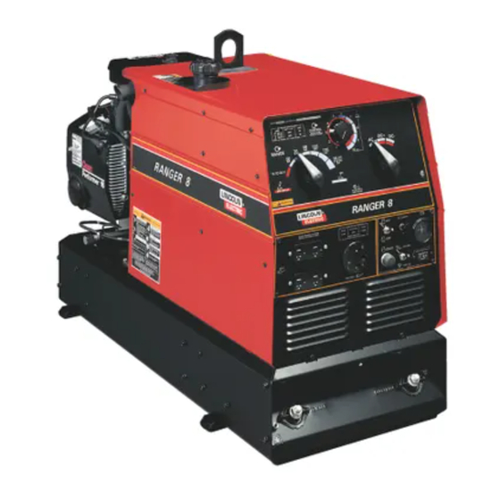
RANGER 10,000 /10,000 PLUS
Safety Depends on You
Lincoln arc welding and cutting
equipment is designed and built
with safety in mind. However,
your overall safety can be
increased by proper installation
. . . and thoughtful operation on
your part. DO NOT INSTALL,
OPERATE OR REPAIR THIS
EQUIPMENT WITHOUT READ-
ING THIS MANUAL AND THE
SAFETY PRECAUTIONS CON-
TAINED THROUGHOUT. And,
most importantly, think before
you act and be careful.
Cleveland, Ohio 44117-1199 U.S.A. TEL: 216.481.8100 FAX: 216.486.1751 WEB SITE: www.lincolnelectric.com
All manuals and user guides at all-guides.com
®
For use with machine code numbers: Kohler 11041, 11151, 11394
SERVICE MANUAL
• World's Leader in Welding and Cutting Products •
• Sales and Service through Subsidiaries and Distributors Worldwide •
SVM168-B
Honda 11095, 11398
Robin/Subaru 11253. 11395
Copyright © Lincoln Global Inc.
April, 2010
Advertisement
Chapters
Table of Contents
Troubleshooting

Related Manuals for Lincoln Electric K1419-5


Summarization of Contents
Safety Depends on You
SERVICE MANUAL
Indicates the document is a service manual.
SAFETY
FOR ENGINE powered equipment
Lists safety measures specific to engine-powered machinery.
ELECTRIC AND MAGNETIC FIELDS may be dangerous
Warns about potential health risks associated with EMF fields.
SAFETY
ELECTRIC SHOCK can kill.
Details precautions to prevent fatal electrical shocks.
ARC RAYS can burn.
Explains how to protect against arc ray exposure.
FUMES AND GASES can be dangerous.
Highlights hazards from welding fumes and gases.
SAFETY
WELDING and CUTTING SPARKS can cause fire or explosion.
Details precautions against fire and explosion risks from welding.
CYLINDER may explode if damaged.
Provides safety guidelines for handling compressed gas cylinders.
SAFETY
PRÉCAUTIONS DE SÛRETÉ
General safety precautions in French.
Sûreté Pour Soudage A L’Arc
French safety measures for arc welding.
PRÉCAUTIONS DE SÛRETÉ POUR LES MACHINES À SOUDER À TRANSFORMATEUR ET À REDRESSEUR
French safety for transformer and rectifier welders.
INSTALLATION
TECHNICAL SPECIFICATIONS - RANGER® 10,000 (K1419-4 ), (K2160-3 ) and (K2468-1)
Lists technical specifications for different engine models.
RATED OUTPUT @ 104°F (40°C)- WELDER
Specifies welding output ratings under hot conditions.
RATED OUTPUT @ 104°F (40°C)- GENERATOR
Specifies generator output ratings under hot conditions.
PHYSICAL DIMENSIONS
Provides physical dimensions of the machine.
INSTALLATION
TECHNICAL SPECIFICATIONS - RANGER 10,000 PLUS (K1419-5 ), (K2468-2)
Lists technical specifications for RANGER 10,000 PLUS models.
RATED OUTPUT @ 104°F (40°C)- WELDER
Specifies welding output ratings for PLUS models.
RATED OUTPUT @ 104°F (40°C)- GENERATOR
Specifies generator output ratings for PLUS models.
PHYSICAL DIMENSIONS
Provides physical dimensions for PLUS models.
INSTALLATION
SAFETY PRECAUTIONS
Lists critical safety warnings and guidelines for installation.
MACHINE GROUNDING
Explains proper grounding procedures for the welder.
SPARK ARRESTER
Discusses the requirement and installation of a spark arrester.
TOWING
Provides recommendations and considerations for towing the equipment.
INSTALLATION
FUEL
Details fuel requirements and safety during fueling.
OIL
Specifies oil type, capacity, and checking procedures.
BATTERY CONNECTIONS
Provides instructions and warnings for connecting the battery.
PRE-OPERATION SERVICE
Advises reading engine manual and performing pre-operation checks.
VEHICLE MOUNTING
Offers guidance on safely mounting the equipment on vehicles.
INSTALLATION
WELDING OUTPUT CABLES
Provides recommendations for welding cable size and length.
ANGLE OF OPERATION
Explains operating angles for the engine and fuel capacity.
LIFTING
Details safe procedures and precautions for lifting the machine.
HIGH ALTITUDE OPERATION
Discusses de-rating and carburetor adjustments for high altitude.
Muffler Relocation
Briefly mentions muffler relocation.
INSTALLATION
LOCATION / VENTILATION
Specifies proper placement for airflow and exhaust venting.
CONNECTION OF LINCOLN ELECTRIC WIRE FEEDERS
Instructions for connecting wire feeders like LN-15 and LN-25.
CONNECTION OF K930-2 TIG MODULE
Details the connection of the TIG module accessory.
ADDITIONAL SAFETY PRECAUTIONS
Reinforces safety measures for operating the welder.
WELDER OPERATION
Outlines basic welder operation and duty cycle.
INSTALLATION
AUXILIARY POWER
Explains the auxiliary power capabilities of the RANGER.
120 V DUPLEX RECEPTACLES
Details the use and specifications of 120V receptacles.
MOTOR STARTING
Discusses starting single-phase motors with the welder.
RANGER® 10,000 Extension Cord Length Recommendations
Provides guidelines for selecting appropriate extension cords.
INSTALLATION
ELECTRICAL DEVICE USE WITH THE RANGER® 10,000 or RANGER® 10,000 PLUS.
Categorizes devices and potential issues when connecting to the welder.
INSTALLATION
AUXILIARY POWER WHILE WELDING
Details permissible simultaneous welding and power loads.
STANDBY POWER CONNECTIONS
Provides instructions for connecting the unit as a standby power source.
INSTALLATION
CONNECTION OF RANGER® 10,000 OR RANGER® 10,000 PLUS TO PREMISES WIRING
Shows the diagram for connecting the welder to building wiring.
OPERATION
SAFETY PRECAUTIONS
Reiterates crucial safety measures before operating the machine.
GENERAL DESCRIPTION
Gives a general overview of the RANGER's construction and capabilities.
WELDER CONTROLS - FUNCTION AND OPERATION
Explains the function and operation of the welder's controls.
ENGINE SWITCH
Describes the operation of the engine start/stop and idle control switch.
OPERATION
“ RANGE” SWITCH
Details how to use the range switch for different welding processes.
“ CONTROL” DIAL
Explains the function of the control dial for current adjustment.
POLARITY SWITCH
Describes the polarity selection for different welding outputs.
RANGER® 10,000 AND RANGER® 10,000 PLUS APPROXIMATE FUEL CONSUMPTION
Provides estimated fuel consumption rates for various operating modes.
OPERATION
STARTING/SHUTDOWN INSTRUCTIONS
Details the correct procedures for starting and stopping the engine.
BREAK-IN PERIOD
Explains engine break-in requirements, oil consumption, and oil change intervals.
OPERATION
STICK (CONSTANT CURRENT) WELDING
Provides instructions and settings for stick welding.
TIG (CONSTANT CURRENT) WELDING
Details settings and requirements for TIG welding with the module.
WIRE FEED WELDING PROCESSES (CONSTANT VOLTAGE)
Explains wire feed welding using specific electrodes.
ARC GOUGING
Describes how to perform limited arc gouging.
OPERATION
Summary of Welding Processes
A table summarizing welding process settings and idle modes.
ACCESSORIES
OPTIONAL EQUIPMENT (Field Installed)
Details various field-installable accessories like trailers and hitches.
ACCESSORIES
STICK
Lists recommended accessory kits for stick welding.
WIRE FEED
Lists recommended wire feeder models and accessories.
TIG WELDING
Lists recommended equipment for TIG welding.
PLASMA CUTTING:
Lists recommended equipment for plasma cutting.
MAINTENANCE
SAFETY PRECAUTIONS
Emphasizes safety measures before performing maintenance.
ROUTINE MAINTENANCE
Outlines daily maintenance checks and procedures.
ENGINE OIL CHANGE
Provides step-by-step instructions for changing engine oil.
ENGINE OIL REFILL CAPACITIES
Lists oil capacities for different engine models.
MAINTENANCE
OIL FILTER CHANGE
Step-by-step guide for changing the oil filter.
AIR CLEANER AND OTHER MAINTENANCE
Covers air cleaner maintenance and other general upkeep.
MAINTENANCE
ENGINE ADJUSTMENTS
Warns against tampering with engine speed settings.
SLIP RINGS
Describes normal wear and inspection of slip rings and brushes.
BATTERY
Provides safety and procedural information for battery handling.
HARDWARE
Mentions the use of English and Metric fasteners.
MAINTENANCE
ENGINE MAINTENANCE PARTS
A table listing part numbers for oil filters, air filters, and spark plugs.
MAINTENANCE
FIGURE D.1 - MAJOR COMPONENT LOCATION
Illustrates the location of key machine components.
THEORY OF OPERATION
Battery, Starter, Engine, Excitation, Rotor, Stator, and Idler Solenoid
Describes the function of key electrical and mechanical components.
THEORY OF OPERATION
ROTOR FIELD FEEDBACK AND AUXILIARY POWER
Explains how rotor field feedback controls auxiliary power output.
THEORY OF OPERATION
WELD WINDING, REACTOR, AND RANGE SWITCH
Explains the role of the weld winding, reactor, and range switch in current control.
THEORY OF OPERATION
OUTPUT BRIDGE, CHOKE, POLARITY SWITCH, AND OUTPUT TERMINALS
Details the function of the output bridge, choke, and polarity switch.
TROUBLESHOOTING & REPAIR SECTION
How to Use Troubleshooting Guide
Explains the methodology for using the troubleshooting guide effectively.
PC Board Troubleshooting Procedures
Provides specific steps for troubleshooting printed circuit boards.
TROUBLESHOOTING GUIDE
OUTPUT PROBLEMS
Addresses issues related to the machine's output functions.
TROUBLESHOOTING GUIDE
OUTPUT PROBLEMS
Continues troubleshooting for output-related issues.
TROUBLESHOOTING GUIDE
OUTPUT PROBLEMS
Details troubleshooting steps for auxiliary power and output problems.
TROUBLESHOOTING GUIDE
OUTPUT PROBLEMS
Troubleshooting steps for low output and auxiliary problems.
TROUBLESHOOTING GUIDE
OUTPUT PROBLEMS
Troubleshooting steps for specific DC and AC output failures.
TROUBLESHOOTING GUIDE
OUTPUT PROBLEMS
Troubleshooting steps for constant voltage welding output.
TROUBLESHOOTING GUIDE
ENGINE PROBLEMS
Troubleshooting steps for engine not idling down correctly.
TROUBLESHOOTING GUIDE
ENGINE PROBLEMS
Troubleshooting steps for engine not going to high idle.
TROUBLESHOOTING GUIDE
ENGINE PROBLEMS
Troubleshooting steps for engine not cranking, shutting off, or losing power.
TROUBLESHOOTING GUIDE
WELDING PROBLEMS
Troubleshooting steps for a cold welding arc.
TROUBLESHOOTING & REPAIR
ENGINE/ROTOR REMOVAL AND REPLACEMENT
Outlines the process for removing and replacing engine or rotor components.
TROUBLESHOOTING & REPAIR
ENGINE/ROTOR REMOVAL AND REPLACEMENT (continued)
Diagram showing component locations for engine/rotor removal.
TROUBLESHOOTING & REPAIR
ENGINE AND ROTOR REMOVAL PROCEDURE
Step-by-step instructions for removing the engine and rotor assembly.
TROUBLESHOOTING & REPAIR
ROTOR REMOVAL PROCEDURE
Specific steps for safely removing the rotor from the crankshaft.
TROUBLESHOOTING & REPAIR
REASSEMBLY PROCEDURE
Steps for correctly reassembling the engine and rotor components.
TROUBLESHOOTING & REPAIR
RETEST AFTER REPAIR
Instructions for retesting the machine after repairs are completed.
TROUBLESHOOTING & REPAIR
AUXILIARY AND FIELD WINDING TEST
Procedure to test AC voltages from stator windings.
TROUBLESHOOTING & REPAIR
AUXILIARY AND FIELD WINDING TEST (continued)
Continues testing procedures for auxiliary windings.
TROUBLESHOOTING & REPAIR
AUXILIARY AND FIELD WINDING TEST (continued)
Continues testing the field winding and provides reassembly steps.
TROUBLESHOOTING & REPAIR
OUTPUT RECTIFIER BRIDGE TEST
Procedure to check for faulty diodes in the output rectifier bridge.
TROUBLESHOOTING & REPAIR
OUTPUT RECTIFIER BRIDGE TEST (continued)
Steps for testing and replacing diodes in the rectifier bridge.
TROUBLESHOOTING & REPAIR
CHARGING CIRCUIT TEST
Procedure to test the flywheel alternator, regulator, and circuitry.
TROUBLESHOOTING & REPAIR
CHARGING CIRCUIT TEST (continued)
Steps for testing the voltage regulator and associated wiring.
TROUBLESHOOTING & REPAIR
ENGINE THROTTLE ADJUSTMENT TEST
Procedure to check and adjust engine operating speeds.
TROUBLESHOOTING & REPAIR
ENGINE THROTTLE ADJUSTMENT TEST (continued)
Step-by-step guide using the strobe-tach method for adjustment.
TROUBLESHOOTING & REPAIR
ENGINE THROTTLE ADJUSTMENT TEST (continued)
Instructions for adjusting throttle using frequency counter and vibratach.
TROUBLESHOOTING & REPAIR
NORMAL OPEN CIRCUIT VOLTAGE WAVEFORM (115 VAC SUPPLY)
Displays typical AC output voltage waveform under specific conditions.
TROUBLESHOOTING & REPAIR
TYPICAL DC WELD OUTPUT WAVEFORM (CV MODE)
Displays typical CV output voltage waveform when machine is loaded.
TROUBLESHOOTING & REPAIR
TYPICAL DC WELD OUTPUT WAVEFORM (CC MODE)
Displays typical DC output voltage waveform when machine is loaded.
TROUBLESHOOTING & REPAIR
TYPICAL AC WELD OUTPUT WAVEFORM
Displays typical AC output voltage waveform when machine is loaded.
TROUBLESHOOTING & REPAIR
ABNORMAL OPEN CIRCUIT WELD VOLTAGE WAVEFORM (CV MODE)
Displays a CV output voltage waveform with a faulty output diode.
TROUBLESHOOTING & REPAIR
ABNORMAL OPEN CIRCUIT DC WELD VOLTAGE WAVEFORM
Displays a DC output voltage waveform with a faulty output diode.
TROUBLESHOOTING & REPAIR
NORMAL OPEN CIRCUIT WELD VOLTAGE WAVEFORM (CV MODE)
Displays a typical CV output voltage waveform under no load.
TROUBLESHOOTING & REPAIR
NORMAL OPEN CIRCUIT DC WELD VOLTAGE WAVEFORM (CC MODE)
Displays a typical DC output voltage waveform under no load.
TROUBLESHOOTING & REPAIR
NORMAL OPEN CIRCUIT AC WELD VOLTAGE WAVEFORM
Displays a typical AC output voltage waveform under no load.
TROUBLESHOOTING & REPAIR
BRUSH REMOVAL AND REPLACEMENT
Step-by-step guide for removing and replacing generator brushes.
TROUBLESHOOTING & REPAIR
BRUSH REMOVAL AND REPLACEMENT (continued)
Continues the procedure for brush removal and installation.
TROUBLESHOOTING & REPAIR
SLIP RINGS
Information on slip ring wear and cleaning procedures.
TROUBLESHOOTING & REPAIR
PRINTED CIRCUIT BOARD REMOVAL AND REPLACEMENT
Outlines the process for removing and replacing the PC board.
TROUBLESHOOTING & REPAIR
PRINTED CIRCUIT BOARD REMOVAL AND REPLACEMENT (continued)
Continues the procedure for removing the printed circuit board.
TROUBLESHOOTING & REPAIR
PRINTED CIRCUIT BOARD REMOVAL AND REPLACEMENT (continued)
Completes the PC board replacement steps and reassembly.
TROUBLESHOOTING & REPAIR
OUTPUT RECTIFIER BRIDGE REMOVAL AND REPLACEMENT
Provides instructions for removing and replacing the output rectifier bridge.
TROUBLESHOOTING & REPAIR
OUTPUT RECTIFIER BRIDGE REMOVAL AND REPLACEMENT (continued)
Continues the procedure for removing the output rectifier bridge.
TROUBLESHOOTING & REPAIR
OUTPUT RECTIFIER BRIDGE REMOVAL AND REPLACEMENT (continued)
Completes the reassembly steps for the output rectifier bridge.
TROUBLESHOOTING & REPAIR
ENGINE/ROTOR REMOVAL AND REPLACEMENT
Outlines the process for removing and replacing engine or rotor components.
TROUBLESHOOTING & REPAIR
ENGINE/ROTOR REMOVAL AND REPLACEMENT (continued)
Diagram showing component locations for engine/rotor removal.
TROUBLESHOOTING & REPAIR
ENGINE AND ROTOR REMOVAL PROCEDURE
Step-by-step instructions for removing the engine and rotor assembly.
TROUBLESHOOTING & REPAIR
ROTOR REMOVAL PROCEDURE
Specific steps for safely removing the rotor from the crankshaft.
TROUBLESHOOTING & REPAIR
REASSEMBLY PROCEDURE
Steps for correctly reassembling the engine and rotor components.
TROUBLESHOOTING & REPAIR
RETEST AFTER REPAIR
Instructions for retesting the machine after repairs are completed.
ELECTRICAL DIAGRAMS
WIRING DIAGRAM - ENTIRE MACHINE - CODE 11041 ONLY - (M20226)
Wiring diagram specific to Code 11041.
ELECTRICAL DIAGRAMS
WIRING DIAGRAM - CODE 11095 ONLY - (M20301)
Wiring diagram specific to Code 11095.
ELECTRICAL DIAGRAMS
WIRING DIAGRAM - CODE 11150 TO 11393 - (M20431)
Wiring diagram for codes 11150 to 11393.
ELECTRICAL DIAGRAMS
WIRING DIAGRAM - CODE 11398 - (M21269)
Wiring diagram specific to Code 11398.
ELECTRICAL DIAGRAMS
WIRING DIAGRAM CODE 11394 AND 11395 (M21270)
Wiring diagram for codes 11394 and 11395.
ELECTRICAL DIAGRAMS
SCHEMATIC - ENTIRE MACHINE - CODES 11395 AND 11398 - (L13105)
Schematic for codes 11395 and 11398.
ELECTRICAL DIAGRAMS
SCHEMATIC - ENTIRE MACHINE - CDE 11394 - (L13103)
Schematic for code 11394.
ELECTRICAL DIAGRAMS
SCHEMATIC - ENTIRE MACHINE - CODE 11095 & 11253 ONLY - (L12257)
Schematic for codes 11095 and 11253.
ELECTRICAL DIAGRAMS
SCHEMATIC - ENTIRE MACHINE - CODE 11151 ONLY - (L12249-1)
Schematic for code 11151.
ELECTRICAL DIAGRAMS
SCHEMATIC - IDLER/FIELD CONTROL P.C. BOARD - CODE 11041 ONLY - (L12049)
Schematic for the idler/field control PC board (Code 11041).
ELECTRICAL DIAGRAMS
SCHEMATIC - IDLER/FIELD CONTROL P.C. BOARD - CODES ABOVE 11050 ONLY - (L12197-1)
Schematic for the idler/field control PC board (Codes above 11050).
Need help?
Do you have a question about the K1419-5 and is the answer not in the manual?
Questions and answers