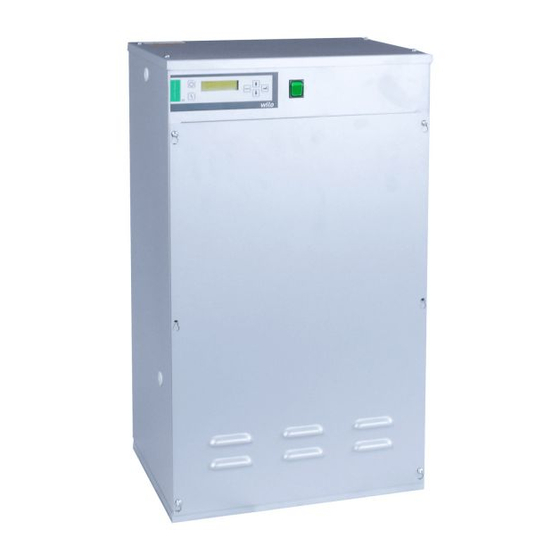
Summarization of Contents
1: Installation
Location
Considerations for pump set positioning including ventilation, frost protection, drainage, security, and access for maintenance.
Foundations
Requirements for foundations, emphasizing level and firm surfaces for pump set stability and avoiding distortion.
Pipework
Guidance on pipework connections, matching set sizes or contacting for advice on smaller connections.
Impurities
Water quality requirements, specifying maximum impurity levels and filter use in suction pipes for dirty water.
Electrical Connections
Checks for compatible supply voltage/frequency and correct wiring, fusing, and earthing according to regulations.
Water Connections
Details on connecting wholesome water supply and system categories, preventing back contamination.
2: Operation
General Operation
Explanation of closed-loop pressure control using transducers and electronic controllers for maintaining constant pressure.
Factory Settings
Overview of default parameter settings for Cold Fill Pressure, alarms, and pump configuration.
Auto Restart
Functionality for automatic unit restart on power up after a mains failure or power downtime.
Low Water
Response to low water levels in the break tank, activating alarms and preventing pump operation.
Low Pressure (LP)
Alarm activation when system pressure drops below the set LP threshold, with options for latching.
High Pressure (HP)
Alarm activation when system pressure exceeds the set HP threshold, with options for latching.
Excess Starts (ES)
Alarm triggered by excessive pump starts within a set time period, stopping pumps.
System Fill (SF)
Function to allow continuous pump operation for system filling or leak testing, overriding leak alarms.
Pump Trip
Alarm and pump stop due to excessive current draw (FLC) during operation.
Pump Fail
Alarm and pump stop when no current is drawn, indicating a failure.
Pump Check
Automatic periodic checks of inactive pump operation by running them briefly.
Alarm Latching
Configuration for manual or automatic resetting of alarms after the condition has cleared.
Alarm Log
Storage and viewing of the last 30 alarm events from the view or user mode.
Volt Free Contacts
Facility for 10 volt-free alarms for remote monitoring, with contact ratings for various signals.


Need help?
Do you have a question about the P260 and is the answer not in the manual?
Questions and answers