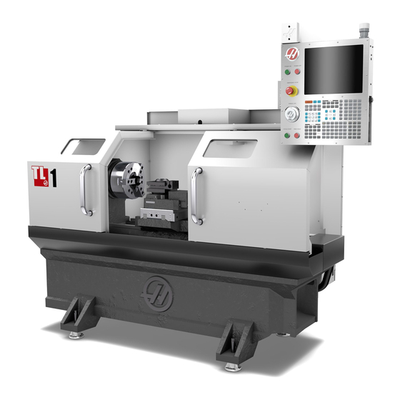
Summarization of Contents
General Safety Guidelines
Workholding Safety Precautions
Safety precautions related to workholding equipment and setup.
Machine Installation Procedures
Shipping Bracket Removal
Steps to remove shipping brackets from TL-1/2/3 and TL-4 models.
Machine Leveling Guide
Procedure for leveling the machine using a machinist's level.
Electrical Requirements and Connections
Input Voltage Specifications
Specifies low and high voltage requirements for different models.
Circuit Breaker Ratings
Lists power supply and Haas circuit breaker ratings for various models.
Service Wiring Gauge
Wire gauge recommendations for short and long electrical service runs.
Ground Wire Safety Warning
Critical information regarding the required earth ground wire connection.
Machine Operation Overview
Power Up and Homing
Procedure for powering on the machine and initial homing.
Tool Turret Removal and Reinstallation
TT-4 (TL-1/2) Turret Removal
Steps to remove the TT-4 tool turret on TL-1/2 models.
TT-4 Tool Turret Realignment
TT-4 Realignment Correction
Correcting alignment errors for the TT-4 tool turret.
TT-10 Turret Alignment Procedures
Squaring TT-10 to Base
Steps to square the TT-10 turret relative to the machine base.
TT-10 Spindle Centerline Alignment
Steps to align the TT-10 turret to the spindle centerline.
TT-10 Runout Correction
Correcting runout for the TT-10 turret.
Manual Mode Operation
X and Z Axes Control
How to control X and Z axes movement using handwheels or jog handle.
Spindle Control
How to command spindle speed and direction.
Machine Position Display Modes
POS-OPER Mode
Operator mode for machine positioning.
POS-WORK Mode
Work coordinate system for part programming.
POS-MACH Mode
Machine coordinate system display.
POS-TO GO Mode
Display of remaining travel distance for axes.
Tool Offset Management
Tool Offset Parameters
Details on tool number, X/Z offsets, wear, radius, taper, and tip.
Automatic Mode Setup
Automatic Mode Parameters
Explanation of parameter input for automatic operations.
Tool Number Input
Entering the active tool number for automatic operation.
Work Offset Selection
Selecting the work offset for part programming.
Z Start Point Entry
Defining the Z-axis starting point for machining.
Workpiece Diameter Input
Inputting the current workpiece diameter.
Diameter to Cut Specification
Specifying the final desired diameter.
Z Dimension Specification
Defining the Z-axis dimension from the start point.
Depth of Cut Setting
Setting the material removal depth per pass.
Feed Per Revolution Setting
Specifying the feed rate per spindle revolution.
Maximum RPM Setting
Setting the maximum spindle speed.
SFM Setting
Inputting the surface feet per minute.
Fillet Radii and Tool Nose
Defining corner fillet radii and tool nose radius.
IPS Recorder Functionality
Select or Create Program
Option to select an existing or create a new program for G-code insertion.
Output G-code to Program
Option to output G-code to the currently selected program.
Alarms and Messages Display
Alarm Display Navigation
Accessing and navigating different alarm screens.
Message Display Management
Accessing and managing operator messages.
Machine Maintenance Overview
Lubrication Procedure
Detailed instructions for lubricating the machine's components.
Lubrication Points and Frequency
Lubrication points and frequency for X/Z axes and tailstock.


Need help?
Do you have a question about the TL-3W and is the answer not in the manual?
Questions and answers