Sign In
Upload
Download
Table of Contents
Contents
Add to my manuals
Delete from my manuals
Share
URL of this page:
HTML Link:
Bookmark this page
Add
Manual will be automatically added to "My Manuals"
Print this page
×
Bookmark added
×
Added to my manuals
Manuals
Brands
Eaton Manuals
Circuit breakers
SPS-616
User manual
Eaton SPS-616 User Manual
Low voltage power circuit breakers for use in ansi/ul applications
Hide thumbs
1
Table Of Contents
2
3
4
5
6
7
8
9
10
11
12
13
14
15
16
17
18
19
20
21
22
23
24
25
26
27
28
29
30
31
32
33
34
35
36
37
38
39
40
41
42
43
44
45
46
47
48
49
50
51
52
53
54
55
56
57
58
page
of
58
Go
/
58
Contents
Table of Contents
Troubleshooting
Bookmarks
Table of Contents
Table of Contents
Purpose
Safety
Section 1: Introduction
General Information
Safety Features
Safety Practices
Figure 1. Family of Magnum PXR Low Voltage Power Circuit Breakers (800-6000 A)
Figure 2. Typical Magnum PXR Nameplate
Table 1 . Magnum PXR Ratings at 240, 480, 600 V
Table 2. Power Defense SB Ratings at 240, 480, and 600V
Qualified Personnel
Other Publications and Documentation
Section 2: Receiving, Handling, and Installation
General Information
Suggested Tools
Unpacking the Circuit Breaker
Figure 3. Typical Magnum PXR and PD-SB Designation Example
Lifting Circuit Breaker
Figure 4. Shipping Clamps for Drawout Circuit Breaker
Figure 5 . Magnum Circuit Breaker with Lifting Yoke Attached (Magnum DS Shown)
Circuit Breaker Inspection
Table 3. Basic Circuit Breaker Weights (Lifting and Support Reference Only)
Installing the Drawout Circuit Breaker
Figure 6. One Side of Drawout Circuit Breaker Properly Seated on Extension Rail
Figure 7. Cassette Rejection Interlock Pin Positioning/Installation
Figure 8. REMOVE Position
Figure 9. DISCONNECT Position
Figure 10. TEST Position
Figure 11. CONNECT Position
Levering Circuit Breaker
Fixed Circuit Breaker
Figure 12. Cassette Label Showing DISCONNECTED, TEST, and CONNECTED Position of Recessed Cover
Figure 13. Levering Position Indication
Circuit Breaker Operation
Section 3: Circuit Breaker Description and Operation
Introduction
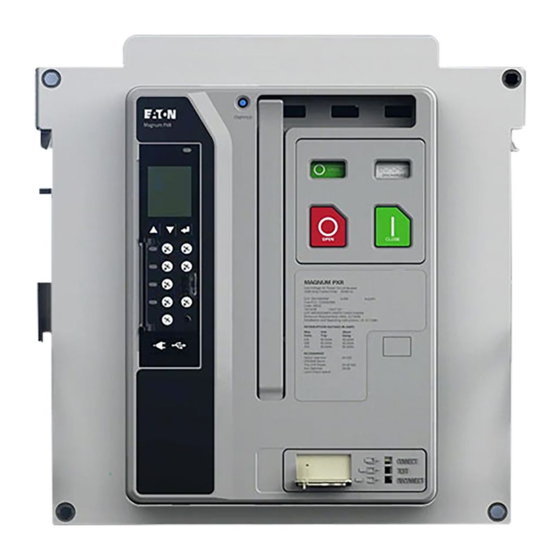
Figure 14. Typical Fixed Magnum PXR Circuit Breaker
Figure 15 . Typical PXR Drawout Circuit Breaker Features (Front and Rear Views)
Figure 16 . Typical PXR Fixed Circuit Breaker Features (Front and Rear Views)
Figure 17 . Typical Double-Wide Standard Frame Circuit Breaker Features (Front and Rear View)
Figure 18 . Magnum PXR and PD-SB Drawout Circuit Breaker
Basic Circuit Breaker Assembly
Pole Units
Figure 19 . Typical Magnum and PD-SB Construction (Right Side View)
Figure 20 . Features of Magnum and PD-SB Moving Conductor Assembly
Figure 21. Narrow Frame (8-Finger) Moving Conductor Assembly
Figure 22. Standard Frame (12-Finger) Moving Conductor Assembly
Figure 23 . General Partial Cross-Sectional View
Operating Mechanism
Figure 24 . Typical Electrically Operated Drawout MPS Circuit Breaker with Front Cover Removed
Figure 25. Circuit Breaker Closing Springs Being Manually Charged (Magnum DS Shown)
Arc Chambers
Figure 26. Electrical Motor Operator to Charge Closing Spring
Figure 27. Cross Section of Conductor and Arc Control System
Figure 28. Integral Arc Runner Viewed from Top of Arc Chamber (Arc Chute Removed, Circuit Breaker Closed)
Electronic Tripping System
Figure 29. Arc Plate Assembly
Figure 30. Pictorial Diagram of Typical Current Sensing, Processing, and Tripping System
Table 4. Magnum PXR and PD-SB Trip Units
Figure 31. PXR 25 Programmable Trip Unit Installed in Magnum PXR Circuit Breaker
Figure 32. Narrow Frame Current Sensors Shown with Cover Plate Removed
Figure 33 . Line and Load-Side Voltage Taps for PXR Circuit Breakers
Accessory Devices
Table 5. Shunt Trip Ratings
Table 6. Continuous Duty Shunt Trip
Table 7. Spring Release Ratings
Figure 34. Through-The-Window Electrical Accessories
Figure 35. Shunt Trip with Cutoff Switch
Figure 36. Shunt Trip Switch Installed
Table 8. Undervoltage Release
Table 9 . Auxiliary Switch, Overcurrent Trip Switch
Figure 37. Spring Release with Optional Latch Switch
Figure 38. Undervoltage Release
Figure 39. Shunt Trip, Spring Release, and Undervoltage Release Installed
Table 10 . Compact Motor Operator
Figure 40. Auxiliary Switch (Form C)
Figure 41. Mechanical Trip Indicator with Associated Overcurrent Trip Switch
Figure 42. Motor Operator Kit
Figure 43. Motor Operator Installed in a Standard Frame Circuit Breaker
Figure 44. Cover Mounted Key Lock and Operations Counter
Figure 45. Cassette-Mounted Key Lock
Figure 46 . OPEN-CLOSE Pushbutton Lockable Cover Plate (Magnum DS Shown)
Figure 47. Typical Safety Shutters in CLOSED Position
Figure 48. Typical Safety Shutters in OPEN Position
Figure 49. Cell Switch (Drawout Position Indicator) Unmounted
Figure 50. Cell Switches Mounted on Cassette
Figure 51. Door Escutcheon and Gasket
Figure 52. IP55 Waterproof Cover (Magnum DS Shown)
Figure 53. Cassette-Mounted Two-Way Cable Interlock (Magnum DS Shown)
Section 4: Master Connection Diagrams
Secondary Contacts and Connection Diagrams
Figure 54 . Secondary Connector Protective Hood
Figure 55. Top View Secondary Connectors
Figure 56. Typical Cassette-Mounted Secondary Wiring
Figure 57. AMP Secondary Wiring Removal Tool
Figure 58 . Magnum PXR and PD-SB 3-Pole Wiring Diagram (PXR20/25)
Figure 59 . Magnum PXR and PD-SB 4-Pole Wiring Diagram (PXR20/25)
Figure 60 . Magnum PXR and PD-SB 6-Pole ABCABC Wiring Diagram (PXR20/25)
Figure 61 . Magnum PXR and PD-SB 8-Pole NABCNABC Wiring Diagram (PXR20/25)
Figure 62 . PXR and PD-SB 6/8 Pole Wiring Diagram (PXR20/25) for Alternate Phasing Configurations
Figure 63. Magnum PXR and PD-SB Accessory Wiring Diagrams (PXR 20/25)
Section 5: Drawout Circuit Breaker and Cassette
General
Figure 64. MPS/SPS Drawout Circuit Breaker in Cassette
Figure 65. MPS/SPS Drawout Circuit Breaker with Automatic Primary Disconnects
Figure 66. Typical Drawout Cassette Features
Drawout Circuit Breaker Dimensions
Drawout Cassette Dimensions
Figure 67. Typical Narrow Frame Cassette (Horizontal Terminals)
Figure 68. Typical Basic Cassette (Vertical Terminals)
Figure 69. Typical Basic Cassette (Without Stabs)
Figure 70 . Typical Universal Cassette, Four-Pole (Flat Terminal Pads)
Section 6: Fixed Circuit Breaker
General
Fixed Circuit Breaker Dimensions
Section 7: Importance of Maintenance
Safety Precautions
Figure 71. Fixed Narrow Frame Circuit Breaker with Available Vertical Adapter Shown
General Cleaning Recommendations
Functional Tests
Figure 72. CLOSED and OPEN Indicators
Procedure
Figure 73. Accessory Viewing Windows
Figure 74. Power Xpert Protection Manager (PXPM) Software
Maintenance Schedule
Table 11. Normal Operating Conditions
Table 12. Normal Maintenance Frequency
Table 13. Increased Frequency Conditions
Table 14. Altitude Rating Factors
Inspection Procedures
Table 15. Pre-Inspection Conditions
Figure 75. Top Rear View of Circuit Breaker with One Arc Chute Removed
Figure 76. Bottom View of Arc Chute
Table 16 . Pre-Inspection Conditions
Figure 77. Primary Contacts with Circuit Breaker Open (Not Used for Contact Wear Inspection)
Figure 78. Contact Inspection Area with Circuit Breaker Open
Table 17 . Pre-Inspection Conditions
Table 18 . Magnum and PD-SB Breaker Torque List
Table 19 . Greases Used on Magnum and PD-SB
Figure 79. Use of Contact Wear Indicator with Circuit Breaker Closed
Figure 80 . Magnum PXR Breaker Mechanism Lubrication
Figure 81 . Magnum PXR Pole Shaft Lubrication
Figure 82 . Magnum PXR Drawout System Lubrication (Not Applicable to Fixed-Mount Breakers)
Figure 83 . Magnum PXR Drawout System Lubrication
Figure 84 . Magnum PXR Charging Handle and Gear Lubrication
Figure 85 . Magnum PXR Pole Shaft and TA Spring Lubrication
Table 20 . Pre-Inspection Conditions
Table 21 . Pre-Inspection Conditions
Figure 86. Primary Disconnects
Figure 87. Breaker Secondary
Figure 88. Cassette Secondary
Table 22 . Pre-Inspection Conditions
Figure 89. Charged and Opened
Figure 90. Push to Close
Figure 91. Levering-In Door in Position between Disconnect and Test
Troubleshooting
Table 23. Spring Charging
Table 24. Contact Closing
Table 25. Contact Opening
Table 26. Levering-In/-Out (Drawout Applications Only)
Section 8: Renewal Parts
General
Disclaimer of Warranties and Limitation of Liability
Advertisement
Quick Links
1
Table of Contents
2
General Information
3
Figure 1. Family of Magnum Pxr Low Voltage Power Circuit Breakers (800-6000 A)
4
Table 1 . Magnum Pxr Ratings at 240, 480, 600 V
Download this manual
User Manual MN013016EN
Magnum PXR and Power Defense SB low
voltage power circuit breakers user manual
For use in ANSI/UL applications
Narrow frame
Standard frame
Effective July 2022
Supersedes January 2022
Double narrow frame
Double-wide frame
Table of
Contents
Previous
Page
Next
Page
1
2
3
4
5
Advertisement
Table of Contents
Need help?
Do you have a question about the SPS-616 and is the answer not in the manual?
Ask a question
Questions and answers
Related Manuals for Eaton SPS-616
Circuit breakers Eaton Cutter-Hammer SPB-50 Instructions Manual
(32 pages)
Circuit breakers Eaton Cutter-Hammer SPB-100 Instructions Manual
(32 pages)
Circuit breakers Eaton SPBT12-280 NPE50 Series Instruction Leaflet
(4 pages)
Circuit breakers Eaton Magnum PXR User Manual
Low voltage power circuit breakers for use in ansi/ul applications (58 pages)
Circuit breakers Eaton SPS-630 User Manual
Low voltage power circuit breakers for use in ansi/ul applications (58 pages)
Circuit breakers Eaton NRX Series Instruction Leaflet
Pop-out trip indicators (10 pages)
Circuit breakers Eaton NRX Series Instruction Leaflet
Breaker pxr trip unit (12 pages)
Circuit breakers Eaton NRX Series Installation And Operating Instructions Manual
Pt module (6 pages)
Circuit breakers Eaton IZMX40 Instruction Leaflet
(30 pages)
Circuit breakers Eaton NRX Series Instruction Leaflet
Drawout and breaker three-way cable interlock installation and removal instructions (10 pages)
Circuit breakers Eaton NRX Series Instruction Leaflet
Installation and removal instructions for drawout breaker two-way cable interlock kit (12 pages)
Circuit breakers Eaton NRX Series Instruction Manual
With pxr. type nf low voltage power (air) circuit breaker (15 pages)
Circuit breakers Eaton NRX Series Instruction Leaflet
Installation/removal instructions for drawout secondary terminal block alignment bracket (8 pages)
Circuit breakers Eaton NRX Series Instruction Leaflet
Spring release, latch check switch and motor operator (29 pages)
Circuit breakers Eaton NRX Series User Manual
Low voltage power (air) circuit breakers (48 pages)
Circuit breakers Eaton SBN-508 Instructions For Installation, Operation And Maintenance
Insulated case low voltage power (70 pages)
Table of Contents
Save PDF
Print
Rename the bookmark
Delete bookmark?
Delete from my manuals?
Login
Sign In
OR
Sign in with Facebook
Sign in with Google
Upload manual
Upload from disk
Upload from URL


Need help?
Do you have a question about the SPS-616 and is the answer not in the manual?
Questions and answers