Table of Contents
Advertisement
I N S TA L L AT I O N , O P E R AT I O N A N D
M A I N T E N A N C E
I N S T R U C T I O N S
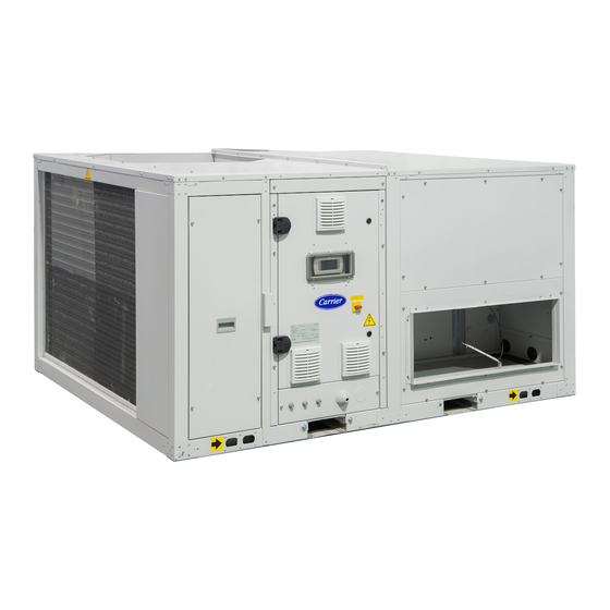
Packaged rooftop units
50FF/FC 020-093
Nominal cooling capacity R-410A 22.3 - 90.2 kW
Nominal heating capacity R-410A 21.9 - 89.7 kW
Nominal cooling capacity R-454B 36.0 - 90.4 kW
Nominal heating capacity R-454B 35.9 - 89.6 kW
Translation of the original document 80185, 03.2022
Advertisement
Table of Contents

Related Manuals for Carrier 50FC 086


Summarization of Contents
2 - SAFETY ADVISE
2.1 - General safety advise
General safety precautions and mandatory regulations for unit operation and maintenance.
4 - TRANSPORT
4.1 - Transport
Specific safety standards for transporting units with R-454B refrigerant.
4.2 - Receipt of goods
Guidelines for checking the condition and parts of the unit upon receipt.
4.3 - Unit identification
Importance of maintaining the visibility of unit markings like name plates and labels.
5 - HANDLING
5.1 - Discharge via forklift truck
Detailed instructions for safely discharging the unit using a forklift truck.
5.2 - Discharge via crane
Instructions and precautions for safely discharging the unit using a crane.
7 - POSITIONING AND INSTALLATION
7.1 - Storage
Recommendations for storing the unit to maintain its condition before installation.
7.2 - Choice of location
Critical considerations for selecting a suitable installation location, including safety and performance factors.
Minimum area for indoor air distribution
Requirements for minimum room area for distributing indoor air from the unit.
Sound Level
Information on sound power and pressure levels, and recommendations for acoustic management.
Removing forklift guards
Instructions for removing forklift guards before installation.
Preparation of the ground
Importance of a flat, level installation surface and planning for fixing points.
7.3 - Antivibrators assembly (silent-blocks)
Detailed procedure for assembling antivibrators (silent-blocks) to the unit base for vibration reduction.
7.4 - Pre-assembly roofcurb (optional)
Installation of an optional pre-assembly roofcurb for unit placement and levelling.
Handling
Procedures for lifting and handling the roofcurb using cranes and slings.
Installation on the roof
Steps for installing the roofcurb on the roof structure and ensuring proper alignment.
Insulation and waterproof sealing
Standard insulation and sealing procedures for the roofcurb to ensure weatherproofing.
Air ducts connections
Recommendations for connecting air ducts to the unit, including profile dimensions.
Positioning the unit on the roofcurb
Steps for correctly positioning and mounting the unit onto the installed roofcurb.
Electric power supply
Routing of power cables to the unit's electrical cabinet.
7.5 - Change in the airflow direction
Instructions for changing the unit's airflow direction from vertical to horizontal on-site.
7.6 - Centres of gravity, weight and reactions in the supports: 50FF series (“Standard”)
B1 assembly
Specific weight and reaction data for B1 assembly models.
B2 and BF assemblies
Specific weight and reaction data for B2 and BF assembly models.
B3 assembly
Specific weight and reaction data for B3 assembly models.
BX assembly
Specific weight and reaction data for BX assembly models.
BP assembly
Specific weight and reaction data for BP assembly models.
BA assembly
Specific weight and reaction data for BA assembly models.
BW assembly
Specific weight and reaction data for BW assembly models.
BT assembly
Specific weight and reaction data for BT assembly models.
BB assembly
Specific weight and reaction data for BB assembly models.
7.6 - Centres of gravity, weight and reactions in the supports: 50FF series (“In-line”)
R1 assembly
Specific weight and reaction data for R1 assembly models.
R2 assembly
Specific weight and reaction data for R2 assembly models.
RP assembly
Specific weight and reaction data for RP assembly models.
RW assembly (machine + recovery module)
Specific weight and reaction data for RW assembly models with recovery module.
7.6 - Centres of gravity, weight and reactions in the supports: 50FC series ("Standard")
B1 assembly
Specific weight and reaction data for B1 assembly models.
B2 and BF assemblies
Specific weight and reaction data for B2 and BF assembly models.
B3 assembly
Specific weight and reaction data for B3 assembly models.
BX assembly
Specific weight and reaction data for BX assembly models.
BP assembly
Specific weight and reaction data for BP assembly models.
BA assembly
Specific weight and reaction data for BA assembly models.
BW assembly
Specific weight and reaction data for BW assembly models.
BT assembly
Specific weight and reaction data for BT assembly models.
BB assembly
Specific weight and reaction data for BB assembly models.
7.7 - Recommended service clearance
50FF/FC 020-028-037-040-045-047: B1, B2 and BF assemblies
Recommended service clearances for specific unit models and assemblies.
50FF/FC 020-028-037-040-045-047: B3, BX, BP and BA assemblies
Recommended service clearances for specific unit models and assemblies.
50FF/FC 020-028-037-040-045-047: BT and BB assemblies
Recommended service clearances for specific unit models and assemblies.
50FF/FC 020-028-037-040-045-047: BW assembly
Recommended service clearances for specific unit models and assemblies.
50FF/FC 052-058-062-070-074-086-093: B1, B2 and BF assemblies
Recommended service clearances for specific unit models and assemblies.
50FF/FC 052-058-062-070-074-086-093: B3, BX, BP and BA assemblies
Recommended service clearances for specific unit models and assemblies.
50FF/FC 052-058-062-070-074-086-093: BT and BB assemblies
Recommended service clearances for specific unit models and assemblies.
50FF/FC 052-058-062-070-074-086-093: BW assembly
Recommended service clearances for specific unit models and assemblies.
50FF/FC 052-058-062-070-074-086-093: R1 and R2 assemblies
Recommended service clearances for specific unit models and assemblies.
50FF/FC 052-058-062: RP assembly
Recommended service clearances for specific unit models and assemblies.
50FF/FC 070-074-086-093: RP assembly
Recommended service clearances for specific unit models and assemblies.
50FF/FC 052-058-062-070-074-086-093: RW assembly
Recommended service clearances for specific unit models and assemblies.
8 - ELECTRICAL CONNECTION
8.1 - Installation norms
Essential safety and regulatory norms for electrical installations.
8.2 - Power supply
Verification of power supply compatibility, voltage stability, and protection measures.
8.3 - Wire sizing
Responsibility and considerations for selecting appropriate wire sizes for electrical installations.
Power cable access routing
Options for routing power cables to the unit's electrical box.
8.4 - Electrical cabinet
Description of the unit's electrical cabinet features and components.
8.5 - "50FC" electronic control
Overview of the "50FC" electronic control system, its components, and connectivity options.
8.6 - Location of sensors on the machine
Specifies the correct positions for various sensors within the unit.
8.7 - Sensors connection by the costumer
Instructions for connecting external sensors like ambient and humidity probes.
9 - FANS AND AIR DUCTS
9.1 - Checks in the axial fans
Steps for checking axial fans before and during operation, including rotation and speed.
9.2 - Checks in the EC plug-fans
Procedures for checking EC plug-fans, including rotation, operation, and characteristic curves.
9.3 - Checks in the centrifugal fans (optional)
Checks for centrifugal fans, including rotation, operation, and characteristic curves.
Pulley and belt calibration
Steps for calibrating pulleys and belts, including alignment and tensioning.
9.4 - Air ducts connections
Recommendations for calculating, designing, and connecting air ducts for optimal performance.
10 - CONDENSATE DRAIN
10.1 - Siphon installation norms
Guidelines for installing a siphon in the condensate drain to prevent smells and spills.
11 - SAFETY ELEMENTS
High pressure switch
Function and activation pressure of the high-pressure safety switch.
Safety valve
Information on the safety valve's presence and activation pressure.
Low pressure safety
How low-pressure safety is managed by the electronic control.
Protection for power lines
Protection devices for compressor and fan power lines against overloads.
Automatic switch in the control circuit
Magnetothermal switch protecting the operation circuit against surges.
Main door switch
Device preventing access to the electrical cabinet when the unit is live.
Defrost control
Safety device to prevent ice accumulation in the outdoor coil during heating.
Safeties at the compressors
Klixon switch and compressor lock safety features.
Control of air flow
How supply plug-fans adapt speed to average flow.
Filter fouling detection (optional)
Differential pressostat for detecting filter clogging.
Condensation and evaporation pressure control
Safety for managing outdoor fans in cooling and heating modes.
Refrigerant leak control
System to detect possible refrigerant leaks for environmental protection.
R-454B Refrigerant leak detector (standard)
Description and function of the standard R-454B refrigerant leak detector.
Anti-fire safety
Anti-fire safety device that stops the unit if return air temperature is too high.
Smoke detector (optional)
Optional smoke detector for safety in certain building types.
Anti-freeze protection for low outdoor temperatures (optional)
Optional protection against low outdoor temperatures for various components.
R-410A Refrigerant leak detector (optional)
Description and function of the optional R-410A refrigerant leak detector.
Remote alarm (optional)
Option for remote alarm signalling management.
12 - FACTORY OPTIONS AND ACCESSORIES
12.1 - Dampers hoods
Installation procedure for fresh air and exhaust air damper hoods.
12.2 - Droplet eliminator at the fresh air intake
Installation of a droplet eliminator at the fresh air intake for high moisture conditions.
12.3 - Fresh air housing (B3, BX, BP, BA, BW, RP 070 to 093, RW assemblies)
Installation procedure for the disassembled fresh air housing.
12.4 - Heat recovery wheel module (BW and RW assemblies)
Transport, handling, and installation of the heat recovery wheel module.
12.5 - Enclosure for lower return (models 052 to 062 with R2 assembly)
Installation of an enclosure for lower air return on specific models.
12.6 - Return fans module (models 052 to 062 with RP assembly)
Transport, handling, and installation of the return fans module.
12.7 - Air filters
Accessing and replacing air filters, including different types and filter holder structure.
12.8 - Heat recovery coil
Installation and connection of the heat recovery coil for pre-heating air.
12.9 - Electrical heaters
Information on auxiliary electrical heaters, their power stages, and safety thermistors.
12.10 - Droplet eliminator after the indoor coil
Installation of a droplet eliminator after the indoor coil for high airflow conditions.
12.11 - Preheater module
Installation of a preheater module (electrical heater) for fresh air intake.
12.12 Hot water coil
Installation and operation of the hot water coil with a three-way valve.
12.13 Gas-fired condensing boiler (only with R-410A)
Installation and characteristics of the gas-fired condensing boiler option.
Safety instructions
Safety instructions for operating and maintaining the gas burner.
Boiler layout
Diagram showing the layout and components of the boiler.
Installation of the boiler
Steps for installing the boiler and connecting its hydraulic circuit.
Gas connections
Requirements and checks for making gas connections to the unit.
Preparation for the condensate drain
Instructions for preparing the condensate drain connection.
Connection at the flue
Requirements for connecting the flue gas burner connections, including materials and incline.
Boiler control panel
Overview of the boiler control panel interface and navigation keys.
Hydraulic circuit
Procedures for filling and emptying the hydraulic circuit of the boiler.
Water quality requirements
Essential water quality parameters for the central heating circuit.
12.14 - Warm air heater module with gas burner
Installation and characteristics of the warm air heater module with gas burner.
Safety instructions
Safety instructions for operating and maintaining the gas burner.
Fuel
Checks and precautions before starting up the gas heater.
Gas leaks
Actions to take in case of gas smell and safety precautions.
Operation
General safety rules and instructions for operating the gas heater.
Maintenance
Maintenance operations and combustion inspections for the gas burner.
Location
Location considerations for the roofcurb with integrated burner.
Delivery of the roofcurb with gas burner
Checks to perform upon delivery of the roofcurb with gas burner.
Burner identification
How to identify the burner and roofcurb using their respective serial numbers.
Connection of the outlet probe
Procedure for connecting the outlet temperature probe to the unit.
Transport and installation
Recommendations for handling and installing the roofcurb with burner.
Electrical connection of the burner
Connecting the burner control to the unit's electrical cabinet.
Connections at the flue
Requirements for flue gas burner connections, including materials and incline.
Terminal configuration
Different types of flue terminal configurations (B23P, C13, C33, C53, C63).
Selection Guide
Guide for selecting flue components based on pressure drop calculations.
Burner condensate drain
Information on the burner condensate drain and its proper connection.
Gas connections
Details on gas connections, including components, pressure, and gas types.
Conversion of burner gas type
Procedures for converting the burner gas type (Natural gas to LPG, G25, etc.).
Analysis of combustion
Steps for analyzing and adjusting combustion parameters like CO₂ levels.
Operating cycle of the burner
Description of the burner's operation cycle, including ignition and modulation.
Turning off the burner
How the burner turns off when heating demand ceases.
Control of the gas burner
How the "50FC" control manages the burner's operation.
Burner protection for low outdoor temperatures (optional)
Optional protection for the burner housing at low outdoor temperatures.
Interface panel
Description of the burner's interface panel for control and diagnostics.
Analysis of Blocks - Faults
Detailed list of faults, their causes, and remedies for the CPU-SMART.
12.15 - Cooling recovery circuit (BA and BB assemblies)
Information about the cooling recovery circuit, its components, and characteristics.
12.16 - Zoning of the air flow
How to manage and control airflow for up to 4 different zones.
Zoning box connections
Description of the zoning box and its connection to the main unit.
Connection of the zone terminals
Electrical connections for zone terminals and communication.
Connection to the electrical cabinet of the 50FF/FC unit
Electrical connections between the zoning system and the unit's electrical cabinet.
13 - COMMISSIONING
13.1 - Checks prior to commissioning
Verification of electrical supply, sensor connections, and crankcase heating.
13.2 - Possible problems at commissioning
Potential operational problems that may occur during commissioning.
13.3 - Operational checks
Checking unit operation, safety devices, and recording operational parameters.
14 - MAINTENANCE
14.1 - General recommendations
General advice for maintenance, including professional servicing and preventive measures.
14.2 - Servicing
Details on Level 1 and Level 2 maintenance tasks.
Level 3 maintenance
Advanced maintenance requiring specialized skills and manufacturer involvement.
14.3 - Access to the main components
Procedures for accessing major components like the compressor.
Compressor
Steps for replacing the compressor, including refrigerant handling and piping.
Oil
Handling, storing, and checking refrigeration oil.
Refrigerant
Information on refrigerants R-410A and R-454B, their properties, and safety.
Periodic check of tightness
Requirements and frequency for performing periodic leak tests.
Additional charge of the optional active dehumidification
Information on active dehumidification and its additional condensation coil.
R-454B refrigerant leak detector (standard)
Detailed explanation of the standard R-454B leak detector and its protection mode.
R-410A refrigerant leak detector (optional)
Information on the optional R-410A refrigerant leak detector and its maintenance.
Active recovery (optional)
Maintenance recommendations for the optional active cooling recovery circuit.
Air coil
Procedures for checking and cleaning the air coils.
Outdoor coil protection grid (optional)
How to access and remove the optional outdoor coil protection grid.
Condensate drain pan
Checking and cleaning the condensate drain pan.
Supply fan in «In-line» units
Accessing the supply fan terminal block in "In-line" units.
Air filters
Filter aspect examination, cleaning, and replacement procedures.
Air filters in the recovery module
Accessing and cleaning air filters within the heat recovery module.
Air filters in the grids of the electrical cabinet
Periodic examination of filters in electrical cabinet grids.
Mixing boxes (optional)
Advising to check the condition of servomotors in mixing box assemblies.
Centrifugal fan (optional)
Checking the cleanliness of centrifugal fans and having spare belts.
Gas burner
Procedures for qualified staff to perform maintenance and combustion checks on the gas burner.
1) Inspection of electrodes
Inspecting and cleaning pilot and detection electrodes.
2) Inspection of flue exhaust and air intake ducts
Visually inspecting flue exhaust and air intake ducts for their status.
3) Inspection and cleaning of the venturi
Inspecting and cleaning the venturi.
4) Inspection and cleaning of the exchanger and burner
Procedures for inspecting and cleaning the exchanger and burner.
5) Inspection and cleaning of the water trap
Cleaning the water trap and checking connections.
6) Inspection of intake gas pressure
Verifying intake gas pressure at the valve corresponds to the required value.
7) Inspection of flame monitoring equipment
Verifying machine faults signalled on the LCD display.
8) Inspection of the safety thermostat(s)
Inspecting the safety thermostat by observing the F20 block signal.
9) Inspection of the ionization current
Checking the ionization current via the LCD display for equipment function.
15 - CONTROL AND ANALYSIS OF BREAKDOWNS
Evaporation pressure very high in relation with the air inlet
Analysis of high evaporation pressure and troubleshooting steps.
Very low condensation pressure
Analysis of very low condensation pressure and troubleshooting steps.
Condensation pressure very high in relation to the air outlet, high pressostat cutoff
Analysis of high condensation pressure and troubleshooting steps.
Evaporation pressure too low (low pressure safety cut-off)
Analysis of low evaporation pressure and troubleshooting steps.
Compressor does not start, does not make noise (humming)
Troubleshooting steps when the compressor does not start or make noise.
Compressor does not start, motor sounds intermittently
Troubleshooting steps when the compressor starts intermittently.
Repeated compressor starts and stops
Analysis of repeated compressor starts and stops and their causes.
The compressor makes a noise
Troubleshooting steps for compressor noise.
Noisy operation
Addressing noisy operation of the unit.
Cycle reversing is not carried out:
Troubleshooting steps when the cycle reversing function is not performed.
No defrosting
Troubleshooting steps when the defrost function is not working.
Does not change winter - summer cycles
Troubleshooting steps when the unit does not change between winter and summer cycles.
Alarm or reading error in the humidity probe (with enthalpic control)
Troubleshooting steps for humidity probe errors.
16 - FINAL SHUTDOWN
Shutting down
Steps for safely shutting down the unit and draining fluids.
Recommendations for disassembly
Guidelines for disassembling the unit for recycling purposes.
Fluids to be recovered for treatment
Information on fluids that need to be recovered and treated.
Materials to be recovered for recycling
List of materials that can be recovered from the unit for recycling.
Waste electrical and electronic equipment (WEEE)
Compliance with WEEE directive for end-of-life equipment management.
Need help?
Do you have a question about the 50FC 086 and is the answer not in the manual?
Questions and answers