Carrier 50FF Series Installation, Operation And Maintenance Instructions
Packaged rooftop units
Hide thumbs
Also See for 50FF Series:
- Control manual (98 pages) ,
- Installation, operation and maintenance instructions (80 pages)
Table of Contents
Advertisement
Quick Links
I N S TA L L AT I O N , O P E R AT I O N A N D
M A I N T E N A N C E
I N S T R U C T I O N S
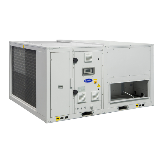
Packaged rooftop units
50FF/FC 100-280
Nominal cooling capacity R-410A 100.0 - 279.9 kW
Nominal heating capacity R-410A 100.2 - 308.4 kW
Nominal cooling capacity R-454B 96,6 - 273,2 kW
Nominal heating capacity R-454B 97,4 - 299,5 kW
Translation of the original document 80576, 11.2022
Advertisement
Table of Contents

Subscribe to Our Youtube Channel
Related Manuals for Carrier 50FF Series


Summary of Contents for Carrier 50FF Series
- Page 1 I N S TA L L AT I O N , O P E R AT I O N A N D M A I N T E N A N C E I N S T R U C T I O N S Packaged rooftop units 50FF/FC 100-280 Nominal cooling capacity R-410A 100.0 - 279.9 kW...
-
Page 2: Table Of Contents
CONTENT 1 - INTRODUCTION .................................... 3 2 - SAFETY ADVISE ................................... 3 2.1 - General safety advise.................................. 3 2.2 - Safety standards for refrigerant ..............................4 3 - POSSIBLE TYPES OF ASSEMBLIES ............................5 4 - TRANSPORT ....................................6 4.1 - Transport ..................................... 6 4.2 - Receipt of goods .................................. -
Page 3: Introduction
1 - INTRODUCTION The 50FF/FC packaged rooftop range consists of autonomous - Electromagnetic Compatibility Directive 2014/30/EU (EMC) compact air-air units of horizontal design, rooftop type. - RoHS Directive 2011/65/EU (RoHS) ■ 50FF R-454B series: Units for cooling operation. - Eco-design Directive 2009/125/EC (ECO-DESIGN) ■... -
Page 4: Safety Standards For Refrigerant
2 - SAFETY ADVISE 2.2 - Safety standards for refrigerant hydrogen chloride and other toxic compounds. These compounds Important: These units contain a fl uorinated greenhouse gas may produce severe physiological consequences if accidentally covered by the Kyoto protocol. inhaled or swallowed. All interventions on the refrigerating circuit must be performed in accordance with applicable legislation. -
Page 5: Possible Types Of Assemblies
3 - POSSIBLE TYPES OF ASSEMBLIES Depending on the indoor airfl ow direction B1 assembly BW assembly Standard Plug-fan in return section S’’ R’’ Heat recovery wheel module (passive recovery) S’ R’ S’ B2 assembly BT assembly Economizer, 2 dampers: Return top box with S’’... -
Page 6: Transport
Do not approach the container or truck in the presence of an open 01120, MONTLUEL, France fl ame, an electrical power source, a mobile phone, or any other UK Importer: Toshiba Carrier UK Ltd, Porsham Close, Roborough, Plymouth, PL6 7DB heat source. - Page 7 5 - HANDLING The unit’s beams are fi tted with the following elements to allow The following drawings show the position in which the transport handling: supports are to be placed: Models 100 to 170: Models 180 to 280: Distances (mm) 50FF/FC 100 to 120 640,5...
- Page 8 5 - HANDLING It is mandatory to follow the lifting instructions given in the drawings Dimensions Centre of gravity Weight provided on the next page. (mm) (mm) (kg) 50FF/FC Length Width Height The centre of gravity is not necessarily in the middle of the unit and 3820 2257 2555...
-
Page 9: Confi Gurations 1 And 3
5 - HANDLING Important: all rigging points must be used 3000 Confi gurations 1 and 3 See detail A Detail A Expander Sling Stretcher Confi gurations 2 and 4 3000 See detail A Detail A Expander Sling Confi gurations 5 and 6 3000 See detail A Detail A... -
Page 10: Operation Limits
5 - HANDLING Correct lifting mode 6 - OPERATION LIMITS Cooling Heating Inlet air conditions 50FF 50FC 50FC Minimum temperature 9,7ºC WB 10ºC (1) With a condensation pressure control disabled operation up to Indoor +12ºC. coil Maximum temperature 24ºC WB 27ºC (2) When the outdoor temperature is usually below 5ºC WB, the Minimum temperature... -
Page 11: Choice Of Location
7 - POSITIONING AND INSTALLATION 7.2 - Choice of location When choosing the location, whatever may be the selected fashion, with fl ammable substances in the form of gas is not likely to occur the following precautions have to be taken into consideration: in normal operation but, if it does occur, will persist for a short period only. -
Page 12: Antivibrators Assembly (Silent-Blocks)
7 - POSITIONING AND INSTALLATION 7.3 - Antivibrators assembly (silent-blocks) Sound Level Although the installer is the one who must decide on a case-by- These units are designed to work with a low acoustic level. In any case basis the best way to place the unit in the ultimate location, case, the following must be taken into account for the design of always in observation of the handling standards that have been the installation: the outdoor environment for acoustic radiation, the... -
Page 13: Pre-Assembly Roofcurb (Optional)
7 - POSITIONING AND INSTALLATION 7.4 - Pre-assembly roofcurb (optional) These units can rest on standardised pre-assembly roofcurbs with adjustable height, built in galvanised steel panelling with polyester paint and thermal insulation. The levelling system uses angle pieces that allow adjustments in the X and Y axes. As a result, the unit will be perfectly levelled on a sloping roof. - Page 14 7 - POSITIONING AND INSTALLATION Handling It is mandatory to use all required PPE for work at height. For transport and lifting up to the roof using a crane, a rocker arm as well as approved slings, both suitable for the dimensions and Place the roof curb on the joists and check that it has been weight of the roof curb, must be used.
- Page 15 7 - POSITIONING AND INSTALLATION The next step will be to check the leveling of the roof curb. The ■ Roof curb with burner: procedure is diff erent for the standard roof curb and for the roof The roof curb is shipped from the factory with its minimum curb with burner: height.
- Page 16 7 - POSITIONING AND INSTALLATION Air ducts connections Insulation and waterproof sealing For units with vertical airfl ow, the ducts must be connected to the Following insulation is standard for the roof curb: profi les from underneath the roof curb. ■...
- Page 17 7 - POSITIONING AND INSTALLATION Passage of the electrical cables through the roof curb Caution: it is strictly forbidden to get onto the roof curb. The power and control cables must pass through the roof curb for The upper part of the sealing must always end under the “L” profi...
- Page 18 7 - POSITIONING AND INSTALLATION Positioning the unit above the roof curb Once the previous work has been carried out, the rooftop unit can No connecting element is necessary between the unit and the roof be positioned above the roof curb with the help of a crane. For curb, because they are perfectly coupled.
-
Page 19: Centres Of Gravity, Weight And Reactions In The Supports
7 - POSITIONING AND INSTALLATION 7.5 - Centres of gravity, weight and reactions in the supports B1 assembly 50FF/ Centre of gravity (mm) Weight Reactions in the supports (kg) (kg) 1566 1046 1430 274 363 127 242 326 100 1566 1046 1450 277 368 129 246 331 102... - Page 20 7 - POSITIONING AND INSTALLATION 7.5 - Centres of gravity, weight and reactions in the supports B1 assembly 50FF/ Centre of gravity Weight Reactions in the supports (mm) (kg) (kg) R1 R2 R3 R4 R5 R6 R7 R8 180 2356 1121 965 2265 258 411 265 191 268 436 253 182 200 2338 1135 947 2370 271 425 273 195 291 455 272 190...
-
Page 21: Recommended Service Clearance
7 - POSITIONING AND INSTALLATION 7.6 - Recommended service clearance Important: This is the minimum space required for maintenance operations and access inside the unit. Depending on the assembly selected for the unit and the characteristics of the installation site, a larger space around it may be required to ensure proper air circulation and therefore the correct operation of the unit. - Page 22 7 - POSITIONING AND INSTALLATION 7.6 - Recommended service clearance Important: This is the minimum space required for maintenance operations and access inside the unit. Depending on the assembly selected for the unit and the characteristics of the installation site, a larger space around it may be required to ensure proper air circulation and therefore the correct operation of the unit.
-
Page 23: Electrical Connection
8 - ELECTRICAL CONNECTION 8.1 - Installation norms ■ The distance between the unit and its power source. ■ The protection to be placed at the power source. Important: All connections in the site are the responsibility ■ Neutral operating conditions. of the installer. - Page 24 8 - ELECTRICAL CONNECTION Models 180 to 280: The following images show the location of these boxes: Models 100 to 170: BOX4 BOX7 BOX3 BOX8 BOX6 Electric cabinet Electric power supply inputs BOX2 BOX1 The fan for cooling the electrical cabinet, the graphic terminal and the ground connector, all located on the doors, must be disconnected before removing the doors.
-
Page 25: 50Fc" Electronic Control
8 - ELECTRICAL CONNECTION 8.5 - “50FC” electronic control 8.6 - Location of sensors on the machine “50FC” electronic control is basically comprised of a control board, Unit 2 circuits sensors, a graphic terminal, an user terminal (optional), a touch Outdoor temperature probe panel (optional) and a BMS card (optional). - Page 26 8 - ELECTRICAL CONNECTION ■ This probe must be fastened to the panel or the wall of the room to be conditioned, at ca. 1.5 m height. Electrical connection ■ Make the electrical connection according to the unit confi guration: - NTC Probe S5a: B5 (connector J3): with 2 x 1,5 mm section cable,...
- Page 27 8 - ELECTRICAL CONNECTION Connection of the CO air quality probe Duct-mounted This version can be connected to the air duct in these two ways: There are diff erent options: ■ Ambient air quality probe. ±0.3 3.54 “ ±0.11 ■ Return air quality probe (duct-mounted). Ø...
-
Page 28: Fans And Air Ducts
9 - FANS AND AIR DUCTS 9.1 - Checks in the axial fans ■ Before commissioning, check the blade rotation direction and that the axis turns without strokes nor vibrations. ■ Before commissioning, check the blade rotation direction and ■ Once running, check the operation conditions: pressures, fl ows that the axis turns without strokes nor vibrations. -
Page 29: Air Ducts Connections
9 - FANS AND AIR DUCTS 9.4 - Air ducts connections Belt tension: After fi xing the pulleys on the same plane, the belt tension is made The air supply and return ducts must be calculated in accordance by tightening the tensor screw. with the nominal fl... -
Page 30: Condensate Drain
10 - CONDENSATE DRAIN These units are equipped with a condensate drainage pan in the Important: the water drain pipe must be CONNECT SIPHON indoor circuit, with a 3/4” M gas threaded plastic drain connection. provided with a siphon to avoid bad smell METTRE SIPHON and water spills. -
Page 31: Safety Elements
11 - SAFETY ELEMENTS High pressure switch ■ High temperature safety in tandem compressors (optional): Working in COOLING mode, when the outdoor coil pressure Connected to the compressor discharge, it will stop its operation of a circuit overcomes a limit value one of the two compressors when the pressure at that point reaches the setpoint. - Page 32 11 - SAFETY ELEMENTS R-454B Refrigerant leak detector (standard) Anti-fi re safety Due to the A2L category of refrigerant R-454B (lightly fl ammable), it The electronic control can activate an anti-fi re safety device that requires the installation of a refrigerant leak detector. This detector detains the unit when the return air surpasses a temperature of uses infrared instead of semiconductor technology with no need 60°C (by default).
-
Page 33: Factory Options And Accessories
12 - FACTORY OPTIONS AND ACCESSORIES 12.1 - Dampers hoods Depending on the assembly chosen, the fresh air and exhaust ■ Step 3: Fasten the reinforcing triangles (4) to the hood (1) using air damper hoods are supplied folded down, to be fi tted on site 5 or 6 screws (depending on assembly). -
Page 34: Heat Recovery Wheel Module (Bw Assembly)
12 - FACTORY OPTIONS AND ACCESSORIES Installation All the screws required for this assembly are supplied in a bag. ■ The fresh air housing (1) is factory-installed. ■ First, the front panel (2) is secured using 8x40 hex screws. ■ Then, in models 100 to 170 the support bed (3) is fi tted. This is fi... -
Page 35: Air Fi Lters
12 - FACTORY OPTIONS AND ACCESSORIES Note: Check that the locks are not blocked. Open them with a Connection to be made by the customer: 4 mm Allen wrench (in an anti-clockwise direction). 50FC unit Wheel module BOX5 BOX3 BOX6 W59RRT Access to the inside of the recovery module ■... -
Page 36: Heat Recovery Coil
12- FACTORY OPTIONS AND ACCESSORIES 12.5 - Heat recovery coil This option is compatible with B1, B2, BT and BB assemblies. W43 (BOX8) Actuator ■ The heat recovery coil (HRC) is placed between the main indoor → coil and the air fi lters. →... -
Page 37: Stop-Drop In The Indoor Coil
12 - FACTORY OPTIONS AND ACCESSORIES 12.6 - Stop-drop in the indoor coil These heaters are accessed by removing the panels (1) and (2), and then the inside panel (3), all of them fi xed with M6 ■ The stop-drop can be installed in the indoor coil. It’s Allen screws. -
Page 38: Hot Water Coil
12 - FACTORY OPTIONS AND ACCESSORIES 12.8 - Hot water coil ■ Hot water coil with a three-way valve managed by the electronic been fi nished successfully. control of the unit. The water coil could be activated in the ■ In case of long unit stops, and forcibly if they happen in the following cases: winter season, the coil must be emptied. -
Page 39: Warm Air Heater Module With Gas Burner
12 - FACTORY OPTIONS AND ACCESSORIES 12.9 - Warm air heater module with gas burner performance levels, as well as high thermal and mechanical Natural or propane gas burner with modulating actuator, in resistance. accordance with the Gas Directive 2009/142/EC, installed inside a pre-assembly roofcurb. - Page 40 12 - FACTORY OPTIONS AND ACCESSORIES Before carrying out any cleaning and maintenance operations, Attention: In compliance with the requirements of the isolate the heater from the mains power supply from the switch Gas Directive 90/396 EEC it is strictly prohibited to located on the electrical system and/or on the shut-out devices.
- Page 41 12 - FACTORY OPTIONS AND ACCESSORIES Connection of the burner condensate drain Note: see the wiring diagram included with the unit for a more detailed information about the wiring. These units are equipped with a junction for draining the burner The following image shows the location of the connection box condensates drain pan.
- Page 42 12 - FACTORY OPTIONS AND ACCESSORIES Connections at the fl ue Important: The fl ue of the gas burner is not supplied with In this case, the standards UNI-CIG 7129 and UNI-CIG 7131 the unit. Its design and installation is the responsibility of require the provision of suitable vents on the walls.
- Page 43 12 - FACTORY OPTIONS AND ACCESSORIES Gas connection Use the gas line connections only with EC certifi ed components. Important: For a correct maintenance, connect the PCH module by means of a seal and swivel gasket. Avoid using threaded The PCH module is supplied complete with a dual gas valve, gas connected directly on the gas connection.
- Page 44 12 - FACTORY OPTIONS AND ACCESSORIES Country table - gas category: ■ between the gas pipe and the Venturi, replace the gas orifi ce plate fi tted (natural gas) with the one supplied with the kit (for LPG); Country Category Gas Pressure Pressure ■...
- Page 45 12 - FACTORY OPTIONS AND ACCESSORIES Analysis of combustion After detecting the pilot fl ame, the equipment opens the main gas valve EV2 [C] to supply gas to the main burner. Wait until the heater is switched on. Check that the heater is After a time of dual functioning of the two burners (pilot and running at maximum power by using one of the two methods below: main), the modulation PCB removes gas from the EVP valve...
- Page 46 12 - FACTORY OPTIONS AND ACCESSORIES ■ Fxx faults: ■ Burner control: The modulation PCB can distinguish between 30 diff erent types The gas burner integrates its own CPU-SMART PCB board of faults. This ensures accurate diagnostics. Also, codes and that manages the operation and the safety devices.
- Page 47 12 - FACTORY OPTIONS AND ACCESSORIES By removing the access door to the inside of the burner, the rdy: the machine is on without burner fl ame; it is waiting CPU-SMART PCB can be seen : for the ON control and/or the heat demand from the room temperature monitoring system.
- Page 48 15 minutes. SMART equipment Entering the second password grants access to third level. Lack of communication This password must be requested directly to “CARRIER between TER equipment TER equipment or CPU- Auto-reset Technical Service”. and CPU for more than...
-
Page 49: Cooling Recovery Circuit (Ba And Bb Assemblies)
12 - FACTORY OPTIONS AND ACCESSORIES 12.10 - Cooling recovery circuit (BA and BB assemblies) Access to the recovery circuit Thermodynamic circuit dedicated to the recovery of the extracted air energy, with independent and proportional control, adapted to Models 100 to 170 the air renewal requirements in order to raise the COP and EER of the unit. -
Page 50: Zoning Of The Air Fl Ow
12 - FACTORY OPTIONS AND ACCESSORIES 12.11 - Zoning of the air fl ow Zoning box connections This option allows the management of the air fl ow of the unit to condition up to 4 diff erent zones with a minimum air fl ow of 35% (all The control board of the air zoning is assembled in a separate of them in same operating mode: heating or cooling). -
Page 51: Commissioning
13 - COMMISSIONING 13.1 - Checks prior to commissioning Models 100 to 170 ■ It is advisable to make a complete sketch of the installation including the location of the unit and all the components used. This will be very helpful for maintenance and repairs to the installation. -
Page 52: Possible Problems At Commissioning
13 - COMMISSIONING Control of the refrigerant charge 13.3 - Operational checks ■ Each unit is shipped with an exact charge of refrigerant for Check the unit operation by verifying the electronic control and proper operation.Refrigerants available are: R-410A or R-454B. the safety devices. -
Page 53: Maintenance
14 - MAINTENANCE 14.1 - General recommendations Level 2 maintenance To ensure optimal effi ciency and reliability of the equipment and This level requires specifi c expertise in electrical, cooling and all its functions, we recommend taking out a maintenance contract mechanical systems. -
Page 54: Access To The Main Components
14 - MAINTENANCE Level 3 maintenance ■ The compressor is fi xed onto the platform with 4 screws. ■ Unscrew the fi xings. Maintenance at this level requires specifi c skills, qualifi cations, tools and expertise. Only the manufacturer, his representative or ■... - Page 55 14 - MAINTENANCE Filter drier Important: units with A2L refrigerant are always equipped with a leak detector with infrared sensor. Consult the ■ The fi lter function is the preserve the cooling circuit clean and chapter “Safety elements”. without humidity, neutralizing the acids that can be found in ■...
- Page 56 14 - MAINTENANCE ■ A logbook must be established for equipment subject to ■ Delay time (by default, 180 seconds): Time so that when a warning appears on the sensor it does not become an alarm. periodic leak tests (verify the registration requirements under national regulations).
- Page 57 14 - MAINTENANCE Condensate drainage pan Air coil ■ These units are equipped with a condensate drainage pan ■ Check that the coil is free from dust and grease. sloped toward the drain. ■ Cleaning the accumulated dust on the coil can be performed Note: This pan is removable for easy cleaning in models 100 to using a soft-bristled brush or a vacuum cleaner perpendicular 170.
- Page 58 14 - MAINTENANCE Air fi lters Tab for displacement of the frames ■ Depending on the installation conditions, the fi lter aspect must be examined to defi ne the cleaning or replacing periodicity. Spare parts should be planned for. Tensioner ■...
- Page 59 CARRIER could not accept liability. To keep the machine effi cient and guarantee a long lifetime of the heater, it is advisable to run some inspections every year, before...
- Page 60 14 - MAINTENANCE 1) Inspection of electrodes 7) Inspection of fl ame monitoring equipment Dismantle the complete pilot fl ame and use a jet of compressed With the heater operating, close the gas tap and verify that the air to clean the mesh and nozzle. Check the integrity of the machine faults, signalled on the LCD display with code F10.
-
Page 61: Control And Analysis Of Breakdowns
15 - CONTROL AND ANALYSIS OF BREAKDOWNS Symptom Cause Solution Evaporation pressure very a) Charge excess a) Collect refrigerant high in relation with the air b) High air temperature b) Verify overheating inlet c) Compressor suction not air tight c) Verify compressor state and replace d) Cycle reversing valve in middle position d) Check that the valve is not clogged. -
Page 62: Final Shutdown
16 - FINAL SHUTDOWN Shutting down Materials to be recovered for recycling Separate the units from their energy sources, allow them to cool ■ Steel then drain them completely. ■ Copper ■ Aluminium Recommendations for disassembly ■ Plastics Use the original lifting equipment. ■... - Page 64 QUALITY MANAGEMENT ER-1740/2000 Order No.: 10576, 11.2022. Supersedes order No.: 03.2022 Manufactured by CARRIER SCS - Rte de Thil, 01120 - MONTLUEL, France Published in the European Union Manufacturer reserves the right to change any product specifi cations without notice.
Need help?
Do you have a question about the 50FF Series and is the answer not in the manual?
Questions and answers