
Related Manuals for Rsrteng IPC-9800MOVTADHS Plus+


Summary of Contents for Rsrteng IPC-9800MOVTADHS Plus+
- Page 1 SECURITY CAMERA TESTER IPC-9800 Plus+ Series User Manual IPC-9800 Plus+ IPC-9800C Plus+ IPC-9800ADH Plus+ IPC-9800ADHC Plus+ IPC-9800ADHS Plus+ IPC-9800ADHSC Plus+ IPC-9800MOVTADHS Plus+ V01.00...
- Page 2 Thank you for purchasing the Rsrteng IP camera tester. Please read the manual before using the IP camera tester and use properly. We have built this user manual in the tester, you can also view it on your tester. For using the IP camera tester safely, please first read the「Safety Information」...
-
Page 3: Table Of Contents
SECURITY CAMERA User Manual Content 1. Safety information ..........................1 2. IP Camera Tester Introduction 2.1 General ............................2 2.2 Model feature comparison ......................3 2.3 Packing list ..........................3 2.4 Function interface ........................4 3. Operation 3.1 Installing the Battery ........................7 3.2 Instrument connection ........................8 3.2.1 IP camera connection ......................8 3.2.2 Analog camera connection ....................9 3.2.3 HD Coaxial camera connection ..................10... - Page 4 SECURITY CAMERA User Manual 3.3.14 HD Coaxial & Analog level test ( *Optional ) .............47 3.3.15 SDI Camera Test ( *Optional ) ................49 3.3.16 CVI camera test ( *Optional ) ................50 3.3.17 TVI camera test ( *Optional ) ................57 3.3.18 AHD camera test ( *Optional ) ................59 3.3.19 NET TOOL PRO......................60 (1)IP address scan ......................60 (2)PING Test ........................61...
- Page 5 SECURITY CAMERA User Manual 3.3.36 RTSP Player ........................94 3.3.37 Hik test tool .........................95 3.3.38 Dahua test tool ......................99 3.3.39 Update ........................105 3.3.40 Office ........................105 3.3.41 LED Flashlight ......................106 3.3.42 Browser ........................107 3.3.43 Notepad ........................107 3.3.44 System Setting......................108 3.3.45 File explorer ......................
-
Page 6: Safety Information
◆ At the manual range, when the value scale to be measured is unknown beforehand, set the range selector at the highest position. ◆ Always be careful when working with voltages above 60V DC or 40V AC, keep fingers behind the WWW.RSRTENG.COM Page.1. -
Page 7: Ip Camera Tester Introduction
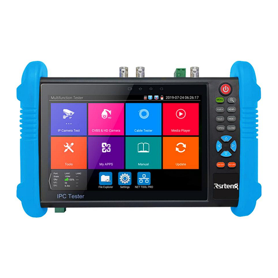
2. IP Camera Tester Introduction 2.1 General The Rsrteng 7 inch touch screen IP camera tester is designed for maintenance and installation of 4K 12MP IP cameras, analog CVBS cameras, 8MP TVI, 8MP CVI, 8MP AHD, 8MP EX-SDI cameras, as well as testing 4K H.264 /4K H.265 camera via mainstream, The 1920x1200 resolution enables it to... -
Page 8: Model Feature Comparison
SECURITY CAMERA User Manual 2.2 Model feature comparison The IPC-9800 Plus+ series has multiple models, this manual lists all the functions of the tester, but does not mean that your tester has all the functions in the user manual. Except for IPC-9800MOVTADHS Plus+, other models will not support some of these functions. -
Page 9: Function Interface
8). Multi-meter test leads one pair of red and black (only for the Multi-meter models) 9). Output Power cable 10). Audio cable 11). TDR alligator clamp (only for TDR models) 12). 8GB SD card 13). Safety cord 14). Tool bag 15). Manual 2.4 Function interface WWW.RSRTENG.COM Page.4. - Page 10 The RS485 data transmission indicator: it lights red while the data is being transmitted The data received indicator: it lights red while the data is being received The power indicator: it lights green while the tester is powered by the adapter WWW.RSRTENG.COM Page.5.
- Page 11 HDMI IN (Optional ) CVBS IN/AHD/TVI/CVI Coaxial interface /(BNC interface) (AHD /TVI/CVI (Optional) ) Video signal output(BNC interface) / cable tracer interface Optical power meter interface (Optional) LED lamp RS485 Interface: RS485communication for the PTZ HD-SDI/EX-SDI input (BNC interface) ( Optional) WWW.RSRTENG.COM Page.6.
-
Page 12: Operation
Notice: When the Charge Indicator turns off, the battery is approximately 90% charged. The charging time can be extended for about 1 hour and the charging time within 12 hours will not damage the battery. WWW.RSRTENG.COM Page.7. -
Page 13: Instrument Connection
Note: 1) If the IP camera requires PoE power, then connect the IP camera to the IP tester's LAN port . The tester will supply PoE Power for the IP camera. Click the icon POE to turn the PoE Power off or WWW.RSRTENG.COM Page.8. -
Page 14: Analog Camera Connection
2) CCTV IP Tester "VIDEO OUT" interface connect to the Video input of monitor and optical video transmitter and receiver, the image display on the tester and monitor. 3) Connect the camera or the speed dome RS485 controller cable to the tester RS485 interface.(Note: positive and negative connection of the cable) WWW.RSRTENG.COM Page.9. -
Page 15: Hd Coaxial Camera Connection
2) Connect the SDI camera or the speed dome RS485 controller cable to the tester RS485 interface. 3.2.4 HDMI IN DVR/NVR or other device's HDMI out port connect to tester's HDMI in port, the meter will display input image. Support 4K 3840x2160P 30fps. WWW.RSRTENG.COM Page.10. -
Page 16: Hdmi Output
TV OUT: Click TV OUT to enter floating window, connecting the BNC cable to tester and appears analog video monitor interface, it can test circuit and BNC cable whether normal. LAN: Display network port or WIFI connection real-time upload and download speeds and other WWW.RSRTENG.COM Page.11. -
Page 17: Short Cut-Menu
You can long press any app in the all applications list, it will auto move to shortcut menu . If delete any app in the shortcut menu, please select a app and press several seconds, it will be deleted. WWW.RSRTENG.COM Page.12. -
Page 18: Screen Capture
Tap icon "Link Monitoring" at left corner on the screen, to enter. It can detect instrument port rate 10/100/1000M, signal quality detection, upload and download speed, etc. in real time. It can be used to detect whether the network video access bandwidth of devices such as NVR is normal. WWW.RSRTENG.COM Page.13. - Page 19 SECURITY CAMERA User Manual When using a four-core cable to connect to a Gigabit device, would prompt "the link limited". Advanced link monitor It is for monitoring CVBS loop, Ethernet statistics, error frame statistics, frame length etc WWW.RSRTENG.COM Page.14.
-
Page 20: Testerplay
IP, then click "Play" to display the real-time image and control IPC Tester. If can’t find the IP address, can click "Manually search for IP", and input tester's rtsp url to remote host IP, such as 192.168.0.186, then click "Play". Please contract supplier for Remote control APP. WWW.RSRTENG.COM Page.15. -
Page 21: Ipc Test Pro
12V power: if the meter turn on, DC12V Auto-turn on, after enter “IPC test pro”, support DC12V power output ,as well display power and voltage of DC12V power supply . (If select box, then exit not turn on PoE ) WWW.RSRTENG.COM Page.16. - Page 22 Click "Sort" to sort by IP in ascending order. Click "Refresh" to search the list again. PING test: After selecting the IP address of the camera, click "Start" to perform a ping test. WWW.RSRTENG.COM Page.17.
- Page 23 3) Double-click the image display area or click "Next" to jump to the ONVIF function. 4) Dahua, Hikvision, and Uniview etc camera can be tested with the corresponding camera test tool on the right side of the IP list. WWW.RSRTENG.COM Page.18.
- Page 24 Video transmission protocol: If the video can’t be displayed when input the correct camera username and password, please try to switch the video transmission protocol. Some cameras only support UDP transmission protocol. More features Click "more" to jump to more function interface. Click “+” icon to add other programs for quick jump. WWW.RSRTENG.COM Page.19.
-
Page 25: Ip Discovery
NON ONVIF: NON ONVIF Quick link Applicability: Using IP discovery app, you don't need to know the first two digits of camera's IP address, it can auto-scan the whole network segment IP, and auto-modify tester's IP address, greatly improved engineering efficiency . WWW.RSRTENG.COM Page.20. -
Page 26: Rapid Onvif Test
If you select ONVIF Rapid mode, the meter automatically scan different network segments for ONVIF cameras. It lists the camera name and IP address on the Device List. Tester can auto login camera and display camera image. WWW.RSRTENG.COM Page.21. - Page 27 Activate HIKVISION Camera: When connected inactivated HIKVISION Camera, tester can auto recognized, and prompt "The camera have not been activated, activated now?", click "OK" to start activate . Pop-up settings menu when click the "ONVIF setting" icon in the upper left corner. WWW.RSRTENG.COM Page.22.
- Page 28 OK: Save the modified parameters. Click "MENU" icon to open camera setting. While in the "Live video" menu, click "Video Menu" at the top right of the image to access the following tools: Snapshot, Record, Photo, Playback, PTZ and Settings. WWW.RSRTENG.COM Page.23.
- Page 29 PTZ rotation direction is displayed on top left corner of the image. IP camera video settings: Click "Video Set" to enter the IP camera's encoder and resolution settings. Make the desired changes and click "OK" to save. WWW.RSRTENG.COM Page.24.
- Page 30 Profiles: Click "profiles", can view video streaming current configuration files, as well as switch between Major stream and minor stream. Preview pictures: Quickly preview and zoom in or out pictures, automatically and manual refresh. Identification: Click "Identification" to view information of the camera. WWW.RSRTENG.COM Page.25.
- Page 31 SECURITY CAMERA User Manual Time set: Click "Time set", Select "Manual set" to set up the time of camera. Maintenance: For camera software reset or restore to factory settings. User Set: Modify camera user name, password etc parameters. WWW.RSRTENG.COM Page.26.
- Page 32 When the image is enlarged, if not operate on touch screen, it can operate by the keyboard, press the to zoon in, press the key to zoom out, press upward and downward key to move image. WWW.RSRTENG.COM Page.27.
- Page 33 Click on the "Stop" icon to stop recording and save the video file to the SD card. Playback: Click the "Playback" icon to view saved videos. Double click the video you want to play. Click to return to the last menu. WWW.RSRTENG.COM Page.28.
- Page 34 Select "default location" in "content location" is without modification. Select "Customization" to arbitrarily adjust the channel name and display location. Click "OK" and the effects will appear. Press return key or click any area of the screen to return to the upper layer of the interface. WWW.RSRTENG.COM Page.29.
- Page 35 Set preset position: Move the camera to preset position, enter the preset number on the Bottom right corner to complete position preset. Call the preset position: Select the preset number on the left, click "Call" to call preset. WWW.RSRTENG.COM Page.30.
- Page 36 SECURITY CAMERA User Manual PTZ Speed set: Horizontal and Vertical Speed set. RTSP: Get RTSP address of the current camera Doc: Auto generate test reports document of camera, click "generate document". Click Preview to view the report document. WWW.RSRTENG.COM Page.31.
- Page 37 SECURITY CAMERA User Manual Enter the camera test information, click "Generate Document" to complete the report. Click "Doc" menu again, you can preview the report document. Icons description: The description of function icons on the bottom toolbar. WWW.RSRTENG.COM Page.32.
-
Page 38: Non Onvif
"Manual": Click IP camera type, list Honeywell, Kodak,Tiandy, Aipu-waton, ACTi, WoshiDA IP camera etc. If the brand has offered official original protocols, pls select camera type, input IP camera address, user name and password, click "official" to enter the camera image display interface(Currently, only support DAHUA official protocols ) WWW.RSRTENG.COM Page.33. - Page 39 IP address. It is better to directly connect the IP camera to the tester so the search results will only display the camera's IP address. If the tester is connected to a PoE switch, it will find and display several IP address. WWW.RSRTENG.COM Page.34.
-
Page 40: Hdmi In ( *Optional )
When tester receives HDMI in image, the top tool bar shows the resolution of this image. You can select "resolution" to set resolution in the setting menu. Tap screen by twice, full image display. Support resolution below 4K_3840×2160-30FPS/2K_2560×1440P/1920×1080p /1920×1080i /720×480p /720×576p /1280 ×720p/1024×768p/1280×1024p /1280×900p /1440×900p WWW.RSRTENG.COM Page.35. - Page 41 (2) Video record When you click the "Record" icon, video starts recording. A red recording icon appears on the screen and begins to flash and a timer appears indicating the time elapsed for the video. Click on the "Record" WWW.RSRTENG.COM Page.36.
- Page 42 Double-tap the image you want to view to make it full screen. Double-click again the photo to return. To rename or delete an image, click and hold on the file until this screen below appears Click to close and return to PTZ controller. WWW.RSRTENG.COM Page.37.
-
Page 43: Analog Camera Test
Video files also can play in the main menu "Video Player". 3.3.11 Analog camera test Analog camera test and PTZ control, click icon to enter Display the input video image, click the top menu bar icon to enter video level meter, (PEAK level, SYNC level, COLOR BURST measurement) WWW.RSRTENG.COM Page.38. - Page 44 Move the yellow cursor to "Baud ", Select the baud rate according to baud rate of the PTZ camera.(150/300/600/1200/2400/4800/9600/19200/57600/115200) D. Address Set the ID according the ID of PTZ camera (0~254), the setting address data must be consistent the speed dome address. WWW.RSRTENG.COM Page.39.
- Page 45 Click icon "set", to enter and set analog video image brightness, contrast, color saturation, as well as the file storage way after snapshot and recording, support auto-storage and manual storage. When select manual storage, user can name and store the files. WWW.RSRTENG.COM Page.40.
- Page 46 , press the key to zoom in, press upward and downward key to move the image. For analog video input, as the resolution is 720*480, it is normal that the zoom in image is not WWW.RSRTENG.COM Page.41.
- Page 47 Chinese character, English letter, or digit) to store in SD card, tester will hereby store the files in SD card after recording. if select "Auto-storage", tester will auto store the files in SD card after recording. WWW.RSRTENG.COM Page.42.
- Page 48 To rename or delete an image, click and hold on the file until this screen below appears. Click to close and return to PTZ controller. (7) Recorded video playback Click the "Playback" icon to view your recorded videos. Tap on the video file image you want to watch. WWW.RSRTENG.COM Page.43.
- Page 49 PEAK to PEAK, SYNC levels and COLOR BURST chroma level. When an analog signal is fed into the meter, the tester displays the measurements on the bottom left corner of the screen While in PAL format, the unit will be mV, While in NTSC format, it will be IRE. WWW.RSRTENG.COM Page.44.
- Page 50 Burst will diminish in amplitude over longer cable runs and can get fall below the threshold for the video display to show a color image. For NTSC format, the Chroma standard level is 40 IRE WWW.RSRTENG.COM Page.45.
-
Page 51: Color-Bar Generator (Tv Out)
Optical, video cables etc. The tester "VIDEO OUT" port to connect optical terminal's sending port, and "VIDEO IN" port to optical terminal's connect its receiving port. WWW.RSRTENG.COM Page.46. -
Page 52: Autohd ( *Optional )
It is used for level measurement of HD coaxial cameras, judge whether the working image of the camera and the image after attenuation by BNC cable transmission are normal, quickly detect and eliminate faults. WWW.RSRTENG.COM Page.47. - Page 53 Threshold: Critical value at this resolution. Lower this value, will appear image noise on the screen, click "value" to modify. Reset: Click "Reset" to reset the reference value and threshold. Create documents: The testing report can save customer information, level meter test information, camera information and Instrument information. WWW.RSRTENG.COM Page.48.
-
Page 54: Sdi Camera Test ( *Optional )
SECURITY CAMERA User Manual 3.3.15 SDI Camera Test ( *Optional ) SDI camera test, Dome camera test and PTZ control, click icon to enter. WWW.RSRTENG.COM Page.49. -
Page 55: Cvi Camera Test ( *Optional )
HD CVI camera, CVI dome camera test and PTZ control, click icon to enter When HD CVI signal input, the tester will display the image resolution on the top bar. Double-taps on the screen to make the image displayed full screen. WWW.RSRTENG.COM Page.50. - Page 56 1920x1080P 30FPS/2560x1440P 25FPS/2560x1440P 30FPS/ 2592x1944P 20FPS / 2960x1920P 20FPS / 3840 x 2160P 12.5/15 FPS (1)PTZ control 1.1 Coaxial PTZ control Click the icon"PTZ"on the right toolbar to do the corresponding setting. "Port": select coaxial control Enter PTZ address to perform parameters setting WWW.RSRTENG.COM Page.51.
- Page 57 Tap left, right, upward and downward on the touch screen to control the PTZ rotation direction, PTZ cameras will rotate accordingly. By two fingers move outward and inward on the touch screen to zoom in and out the PTZ. WWW.RSRTENG.COM Page.52.
- Page 58 Setup preset position, move the PTZ camera to the preset position, the Tap it and input preset position number. Tap "Set position" to complete set preset position. Call preset position Tap the preset position: Tap the preset position area, input preset position number. Tap "call position" to complete call preset position. WWW.RSRTENG.COM Page.53.
- Page 59 SECURITY CAMERA User Manual 1.2 RS485 control (1)Operation instructions, please refer to "3.3.1 PTZ (1) PTZ control parameters setting". WWW.RSRTENG.COM Page.54.
- Page 60 Tap icon "UTC", select "menu setting" to enter the dome camera menu. Input calling dome camera menu address code, after finishing the parameter settings, you can press the or click the icon to call the dome camera menu. WWW.RSRTENG.COM Page.55.
- Page 61 (3) Snapshot, record, photo viewer and video play back, please refer to "3.3.1 PTZ (1) Video monitor test". Tap "close menu" or press the key " " to close camera menu. (4) Save setting Click icon "Set" on the right toolbar to enter storage setting. Support auto-storage and manual storage. WWW.RSRTENG.COM Page.56.
-
Page 62: Tvi Camera Test ( *Optional )
The tester supports resolution as follows: 1280x720P 25FPS / 1280x720P30FPS / 1280x720P 50FPS / 1280x720P 60FPS 1920x1080P 25FPS / 1920x1080P 30FPS / 1920x1080P 50FPS / 1920x1080P 60FPS //2048x1536P 18FPS/2048x1536P 25FPS/2048x1536P 30FPS /2560x1440P 15FPS/2560x1440P 25 FPS/2560x1440P 30FPS/2688x1520P 15FPS/2592x1944P 12.5FPS/2592x1944P 20FPS/3840 x 2160P 12.5/15 FPS WWW.RSRTENG.COM Page.57. - Page 63 Input calling dome camera menu address code, after finishing the parameter settings, you can press the or click the icon to call the dome camera menu. More operation instructions (such as PTZ control, coaxial camera menu setting, snapshot, recording and playback etc), please refer to "3.3.6 CVI camera test". WWW.RSRTENG.COM Page.58.
-
Page 64: Ahd Camera Test ( *Optional )
UTC control: select "PTZ control or PTZ control-2"(AHD camera has two different order, if select "PTZ" cannot control, please go "PTZ-2" ) If to coaxial PTZ control the AHD camera, no parameters setting is needed. More operation instructions please refer to "3.3.6 CVI camera test" WWW.RSRTENG.COM Page.59. -
Page 65: Net Tool Pro
Connect the cable to the LAN port. Set your IP address search range by changing the Start and End IP addresses. Click the "Start" button to scan the IP address range. You can also input an IP address in the Port Number Scan to scan for open ports. WWW.RSRTENG.COM Page.60. -
Page 66: 2)Ping Test
To use the Network tester, you will need two IP testers. One is used as a Server and the other as a Client. Both devices must be on the same network segment in order to communicate. Click the icon to open the Network Tester app. WWW.RSRTENG.COM Page.61. - Page 67 Start send packet test: Using the other IP tester, type in the Server's IP address at the top right corner of the screen. This app is used to send packets for network speed testing. Click the "Start" button to send the packets and start testing. WWW.RSRTENG.COM Page.62.
- Page 68 Tester as Client, tester's IP address is:192.168.0.238. The Server and the Client are at the same network segment, but with different IP address. Input Server's IP address 192.168.0.39 in the tester and click "Start" to test network bandwidth. WWW.RSRTENG.COM Page.63.
-
Page 69: 4)Port Flashing
Click "Start". The IP tester sends a unique signal to make the connected LAN port of the switch flash. If the tester and PoE switch are connected well, the LAN port of POE switch flash at special frequency, If not, no any changes on the LAN port WWW.RSRTENG.COM Page.64. -
Page 70: 5)Dhcp Server
Click on the DHCP icon to open the DHCP server app. Select the "Start" check box at the top and make any desired changes to the network settings. Click "Save" to start assigning dynamic IP addresses for IP cameras and other networked devices. Click the "Refresh" button to check your Client list. WWW.RSRTENG.COM Page.65. -
Page 71: 6)Trace Route
Link Monitor list, click "Start". If the IP address status shows a check mark the IP address is occupied. If the IP address status shows an X the IP address is available. Click "Stop" to stop the testing WWW.RSRTENG.COM Page.66. -
Page 72: Poe Power / Dc12V 3A And Dc 5V 2A Usb Power Output
Supports PoE, the PoE power is delivered via pins 1, 2, 3, and 6 on the LAN port. The IP tester will display "48V ON" at the top of the screen when the POE power is still on. WWW.RSRTENG.COM Page.67. -
Page 73: Dc 24V 2A Power Output
The top and the bottom of the "DC24V ON/0W "is power output interface Application: Power output function is mainly used in the camera field demonstration and testing, meanwhile, for some camera installation sites, if there is no power outlet, the tester can offer temporary power for the camera. WWW.RSRTENG.COM Page.68. -
Page 74: Cable Test
Connect LAN cable or telephone cable with the CCTV tester and cable tester. And then the connecting status, cable type and the sequence of wires as well as the serial number of the cable tester kit will be displayed. The number of the cable tester is 255. WWW.RSRTENG.COM Page.69. - Page 75 Tester / Cable tester is faulty, and the middle of the cable is normal. Tester-end can performRJ45 cable connector fault detection even when the remote end is not connected to the cable tester's UTP interface. WWW.RSRTENG.COM Page.70.
- Page 76 Cable test Tap "cable test sketch map", pop up Straight-through cable and crossover cable sketch, It is for line sequence reference, when the crystal on the first pressure in the twisted-pair. WWW.RSRTENG.COM Page.71.
-
Page 77: Rj45 Cable Tdr Test
"online", the testing result would be not accurate. Cable quality test: Green is good quality cable, Yellow is Poor quality cable, Red is water poured cable, the attenuation value will be displayed when cable over 10 meters. WWW.RSRTENG.COM Page.72. - Page 78 Skew: After 1000M link up, when skew value is 0ns, it is the best quality communication, if over 50ns, will cause a Bit Error Rate in the transmission. Cable sequence diagram: A straight- through and cross-over cable diagram, the cable sequence display for reference. Click "Help" to check the instruction of all parameters. WWW.RSRTENG.COM Page.73.
-
Page 79: Cable Tracer ( *Optional )
Press the "MUTE" button of cable tracer for 2 seconds. After the "Di" sound, the silent mode is turned on. In the silent mode, can judge cable type according to the indicator light. Press the "MUTE" button again to exit the silent mode. WWW.RSRTENG.COM Page.74. -
Page 80: Tdr Cable Test ( *Optional )
Connect Alligator clip cable to the TDR port, and the cable must connect well before testing, otherwise it will influence the accuracy. Built-in BNC cable, network cable, RVV control cable, Telephone line and TVVB cable etc can test. 11 groups user-defined cable can be set. WWW.RSRTENG.COM Page.75. - Page 81 Click "Cable" "Type" to select cable and start testing. One tap on "Start", do one testing. If select built in cable type for testing, click "+" and "-" to adjust cable's wave speed. WWW.RSRTENG.COM Page.76.
- Page 82 "BNC", if testing communication cable 75-2, select SYV 75-2. 3. Click "+" or "-" to adjust wave speed, while display length is the same with the actual Length, click "Save" to save calibration data. It can be used for the same cable testing next time. WWW.RSRTENG.COM Page.77.
-
Page 83: Bnc Attenuation Test ( *Optional )
Test Methods: 1.Connect the two alligator clip cables to the CVBS IN port and CVBS OUT port separately. Two crocodile clips red to red and black to black clip together, then click "calibration" to calibrate it. WWW.RSRTENG.COM Page.78. - Page 84 2.After calibration, the red clip clips the copper core of the BNC cable, and the black clip clips the outer envelope of the BNC cable. attenuation value will be displayed after connection, as below: 3.Click "Reset", the application will restore factory defaults. WWW.RSRTENG.COM Page.79.
-
Page 85: Poe Voltage Test
LAN port, tester not only can transmit voltage to supply power for camera, but also transmit data at the same time. as well as the computer connect to the PoE/PSE, it can log in connected tester's PoE camera. WWW.RSRTENG.COM Page.80. -
Page 86: Power Input Test
Warning: Not allow connect device with input power over 17V to tester "12V IN" port, otherwise it will damage the machine. 3.3.29 Digital Multi-meter ( *Optional ) Click icon to enter. WWW.RSRTENG.COM Page.81. - Page 87 Connect the black test lead to the "COM " jack and the red test lead to the "V/Ω" jack. b. Select , enter the DC voltage measurement. c. the tester default Auto range status ,by click "DC auto range" , press the key can select manual range and restore auto range . WWW.RSRTENG.COM Page.82.
- Page 88 Connect the black test lead to the "COM " jack and the red test lead to the "mA" jack for a maximum of 660mA current. For a maximum of 10A, move the red lead to the 10A jack. b. Select , enter the DC current measurement, the screen display"DC current ", can select manual WWW.RSRTENG.COM Page.83.
- Page 89 Connect the black test lead to the "COM" jack and the red test lead to the"mA" jack for a maximum of 660mA current. For a maximum of 10A, move the red lead to the 10A jack. WWW.RSRTENG.COM Page.84.
- Page 90 Connect the black test lead to the "COM " jack and the red test Ω lead to the "V/ " jack. Ω b. Select Ω, enter the measurement he tester default Auto range status, Press the key manually select range, press "NEAR" to restore "Auto range" WWW.RSRTENG.COM Page.85.
- Page 91 Ω the "V/ " jack. (the red lead anode "+" ) b. Select , enter the diode testing. c. Connect test red lead across to the anode, the black lead to the cathode of the diode under testing. WWW.RSRTENG.COM Page.86.
- Page 92 Note: The capacitance of a capacitor should be tested separately, should not test in the installation of circuit. To avoid electric shock, be sure the capacitors have been discharged fully before measuring the ca pacitance of a capacitor. WWW.RSRTENG.COM Page.87.
- Page 93 You can't input the voltage which more than 660V AC, it's possible to show higher voltage, but it's may destroy the inner circuit. Resistance, Continuity, Diode, PTC component Protection Wrong input voltage, will Auto enter protection state , It only suitable for short and limit time work. WWW.RSRTENG.COM Page.88.
-
Page 94: Optical Power Meter ( *Optional )
Note: Please keep the fiber connector and the dust cap be clean, and clean the detector with the special alcohol. Data hold While testing, click "Hold" to data hold, the data will not change. It's convenient to read. Press again to quit. WWW.RSRTENG.COM Page.89. - Page 95 Input another optical fiber to be measured, the displayed new measurement and relative value is red color. Press it again to quit. Data hold and Relative measuring use together, the data is yellow while the function is effect. WWW.RSRTENG.COM Page.90.
-
Page 96: Visual Fault Locator ( *Optional )
60 mins and 120 mins). Click "Steady mode", red laser source emits steady, click again to quit. Click icons "Evasive 1Hz"or "Evasive 2Hz" to enter pulse mode, the red laser source is emitted by a certain frequency, press it again to quit WWW.RSRTENG.COM Page.91. -
Page 97: Audio Record
Controller can check the status of the RS485 transmission through the code on the display. (The RS485 communication rate must be the same.) Application: Check the RS485 communication states of the video optical transmitter whether normal. Engineer can analyze the protocol and check the data through the displayed code. WWW.RSRTENG.COM Page.92. -
Page 98: Audio Player
SD card. Click on the desired file to play. Click RETURN to exit. To rename or delete an existing file, press the file name for a few seconds until the screen below appears. You can then rename or delete the file by pressing the desired option. WWW.RSRTENG.COM Page.93. -
Page 99: Rtsp Player
From the main menu, select the "APP Tool" folder and then select the "RTSP Player" to open the app. If the IP camera uses MJPEG, select the RTSP icon. If the IP camera uses H.264, select the "RTSP HD" icon. Local IP: This is the IP testers IP address. WWW.RSRTENG.COM Page.94. -
Page 100: Hik Test Tool
Hik test tool app is design for activating and debugging Hikvision camera, can auto-identify inactivated hikvision camera, also can display image from the Hikvision camera. Tap icon to enter 1.Activation: Select left [online detection] to display the "inactivated" camera and click activate. WWW.RSRTENG.COM Page.95. - Page 101 Play: Security status shows the "activated" camera. Enter the correct camera password in the right [password] and click [play] to pop up the "private protocol" or "speed ONVIF" two options. Select the protocol you need to see the camera images. WWW.RSRTENG.COM Page.96.
- Page 102 Select "default location" in "content location" is without modification. Select "Customization" to arbitrarily adjust the channel name and display location. Click"OK"and the effects will appear. Press return key or click any area of the screen to return to the upper layer of the interface. WWW.RSRTENG.COM Page.97.
- Page 103 Modify network information: Support "modify" and "batch modify" camera IP address, subnet mask and other parameters modification. Enter a new IP address and subnet mask, the default gateway will be auto modified according to the IP address. Click "OK" to save the changes. WWW.RSRTENG.COM Page.98.
-
Page 104: Dahua Test Tool
3.3.38 Dahua test tool Dahua test tool is developed for installation and debugging of the Dahua IP camera, it can display image, and modify IP, user name and password etc. Making Dahua camera test more convenient and quickly. WWW.RSRTENG.COM Page.99. - Page 105 SECURITY CAMERA User Manual Activation: select left [online detection] to display the "inactivated" camera and click activate. Activate and Batch activate are optional, support reserved phone number for resetting password. WWW.RSRTENG.COM Page.100.
- Page 106 Play: When mode display "activated" camera, input correct password, click "Play" poping up "private protocol" and "ONVIF", Select correspond protocol to view the camera image. Modify Channel: Click "Modify Channel", will pop up OSD setting, includes time, channel name,etc WWW.RSRTENG.COM Page.101.
- Page 107 After selected Channel name, can edit channel name, modify the display position and font size. If select "Default position" of Content location, then no need to modify. If select "customize", then can modify Channel name and display position, click "OK"to view the image. Click "Back" or "Return" button to return previous interface. WWW.RSRTENG.COM Page.102.
- Page 108 SECURITY CAMERA User Manual Modify Network: Support Modify and batch modify two way, can modify camera IP address, Subnet mask and gateway. Input new IP address, need to input password, click "OK" to save the modification WWW.RSRTENG.COM Page.103.
- Page 109 Modify user information: Modify camera user name and password, which is onvif, Dahua test tool, IPC TESTE user name and password, not web user name and password. Factory reset setting: Camera will be soft reset, and the device's user name, password and network set be saved. Other settings information is factory reset. WWW.RSRTENG.COM Page.104.
-
Page 110: Update
Update online: Before using online update, need enter settings-user management to register first. System update: Connect the Internet to update systems. 3.3.40 Office Quick office app (support excel, word, ppt format) doc. editable WWW.RSRTENG.COM Page.105. -
Page 111: Led Flashlight
Click the Time Setting button to set a timer that will shut off the lamp. WWW.RSRTENG.COM Page.106. -
Page 112: Browser
"Settings" app from the main menu to change the IP tester's network settings to match those of the IP camera. 3.3.43 Notepad Notepad can be used to record the important testing results, click the key "Save" to save the contents. Notepad can auto record the storage date and time. WWW.RSRTENG.COM Page.107. -
Page 113: System Setting
SECURITY CAMERA User Manual Please click to view the notepad, all saving contents display. Click each record bar to show the details. Press the record bar for several seconds, prompt whether delete it. 3.3.44 System Setting Click icon to enter WWW.RSRTENG.COM Page.108. - Page 114 IP setting: Manually set the IP address, Subnet Mask, Default Gateway and DNS address or select "Dynamic allocation" to use DHCP. To test multiple network segments, click "Advanced " and then click "Add " to enter another IP address for the IP tester. WWW.RSRTENG.COM Page.109.
- Page 115 WLAN Net: Turn WiFi off or on by pressing the "Open the wifi" button. Once WiFi is turned on, and click connected WIFI, it will scan for wireless networks in your area. Select and press "WIFI" several seconds, to set static IP address. WWW.RSRTENG.COM Page.110.
- Page 116 Start the FTP server and then input the tester's FTP address in the PC's address bar. This will enable the PC to read, copy and edit the files from the SD card without the use of SD card reader. WWW.RSRTENG.COM Page.111.
- Page 117 Modify Lock screen password, you need input lock password again. Select password Lock screen or pattern Lock screen to reset lock screen password. After reset pattern lock screen, you need to draw a new lock pattern. WWW.RSRTENG.COM Page.112.
-
Page 118: File Explorer
Click "File" on the top bar tool, can select internal or external storage. Click on the upper right corner Icon"... ". will pop-up menu, you can select other operation or exit. Browse It includes Music, Videos, Pictures, Documents, zip file etc. It is convenient to view and manager. WWW.RSRTENG.COM Page.113. -
Page 119: Theme
Pressing square area's any color icon several seconds, the selected color icon will be auto move the rectangle area, if you press selected color several seconds, and it will be auto deleted. Theme colors include fixed order and random order, and click "set" to save. WWW.RSRTENG.COM Page.114. - Page 120 When set background color, you can select colors from Color Phase, and also can input color's RGB to set. After finished color setting, click "set" to set it as desktop or application background. Set as desktop background: Setting color as desktop background. Set as application background: Set color as application background. WWW.RSRTENG.COM Page.115.
-
Page 121: Audio Test
IP Camera Tester【*】models Optional Model Display 7 inch retina touch screen, 1920*1200 resolution Network port 10/100/1000Mbps auto adjust, RJ45, Dual LAN port Built in WIFI, speeds 150M, allows you to connect to a wireless network WIFI and view IP cameras WWW.RSRTENG.COM Page.116. - Page 122 2960x1920 20fps, 3840x2160 12.5/15 fps. UTC control and call OSD menu 1 channel TVI input(BNC interfce),resolution support 720P TVI video signal test* 25/30/50/60fps, 1080P 25/30fps, 2048x1536P 18/25/30fps, 2688x1520P (Optional) 15fps, 2560x1440P 15/25/30fps, 2560x1944P 12.5/20fps, 3840 x 2160 12.5/15 fps, UTC control and call OSD menu WWW.RSRTENG.COM Page.117.
- Page 123 PoE power switch, IP setting, WLAN switch, HDMI IN functions etc screen drop-down menu lock, password lock screen or pattern lock 1 ch audio signal input and 1 ch audio signal output to connect headphones Audio test WWW.RSRTENG.COM Page.118.
- Page 124 5/6 cable’s length and short circuit. measurement range 1.2KM *(Optional) Through hardware high-speed sampling and processing technology, test the BNC attenuation test BNC coaxial cable transmission attenuation value, detect the transmission *(Optional) quality of BNC cable. POWER WWW.RSRTENG.COM Page.119.
-
Page 125: Multi-Meter Specifications
Conversion rate: 3times/s Current modes for clamp meter with ZERO function Isolation: the Multi-meter connector must be isolated with the other connector. DC voltage Range Accuracy Resolution 660mV (Manual range) 0.1mV 6.600V ± (0.3%+4) 66.00V 10mV 660.0V 100mV WWW.RSRTENG.COM Page.120. - Page 126 660.0mA 100uA ± (1%+5) 10.00A 10mA AC current Range Accuracy Resolution 6.600mA ± (0.5%+3) 66.00mA 10uA 660.0mA 100uA ± (1%+5) 10.00A 10mA Resistance Range Accuracy Resolution 660.0Ω 0.1Ω ± (0.8%+5) 6.600KΩ 1Ω 66.00KΩ 10Ω ± (0.8%+2) 100Ω 660.0KΩ WWW.RSRTENG.COM Page.121.
- Page 127 0.1Ω sound Diode Range Resolution Function Schottky diode:0.15~0.25V 2.0V rectifier diode:0.6~1.0V triode PN junction:0.5~0.8V Capacitance Range Accuracy Resolution ± (0.5%+20) 6.600nF 66.00nF 10pF 660.0nF 100pF ± (3.5%+8) 6.600μF 66.00μF 10nF 660.0μF 100nF 1μF ± (5%+8) 6.600mF 10μF 66.00mF WWW.RSRTENG.COM Page.122.
-
Page 128: Optical Power Meter Specifications
Working Temperature Operating Temperature -20℃~+70℃ The data above is only for reference and any change of them will not be informed in advance. For more detailed technical inquiries, please feel free to call the Technical Department of our company. WWW.RSRTENG.COM Page.123. -
Page 129: Contact Us
The data above is only for reference and any change of them will not be informed in advance. You can get more information and support by: Website: www.rsrteng.com Sales department: sales@rsrteng.com After-sales service department: service@rsrteng.com Tel: +86-755-32974680 Thank you! WWW.RSRTENG.COM Page.124.
Need help?
Do you have a question about the IPC-9800MOVTADHS Plus+ and is the answer not in the manual?
Questions and answers