Advertisement
WARNING!
Carefully read the manual before the installation or use.
This equipment is to be installed by qualified personnel, complying to current standards, to
avoid damages or safety hazards.
Before any maintenance operation on the device, remove all the voltages from measuring and supply inputs and
short- circuit the CT input terminals.
The manufacturer cannot be held responsible for electrical safety in case of improper use of the equipment.
Products illustrated herein are subject to alteration and changes without prior notice. Technical data and
descriptions in the documentation are accurate, to the best of our knowledge, but no liabilities for errors, omissions
or contingencies arising there from are accepted.
A circuit breaker must be included in the electrical installation of the building. It must be installed close by the
equipment and within easy reach of the operator. It must be marked as the disconnecting device of the
equipment: IEC /EN 61010-1 § 6.11.3.1
Clean the device with a soft dry cloth; do not use abrasives, liquid detergents or solvents.
ATTENTION!
Lire attentivement le manuel avant toute utilisation et installation.
Ces appareils doivent être installés par un personnel qualifié, conformément aux normes en vigueur
en matière d'installations, afin d'éviter de causer des dommages à des personnes ou choses.
Avant toute intervention sur l'instrument, mettre les entrées de mesure et d'alimentation hors tension et court-
circuiter les transformateurs de courant.
Le constructeur n'assume aucune responsabilité quant à la sécurité électrique en cas d'utilisation impropre
du dispositif.
Les produits décrits dans ce document sont susceptibles d'évoluer ou de subir des modifications à n'importe
quel moment. Les descriptions et caractéristiques techniques du catalogue ne peuvent donc avoir aucune
valeur contractuelle.
Un interrupteur ou disjoncteur doit être inclus dans l'installation électrique du bâtiment. Celui-ci doit se trouver
tout près de l'appareil et l'opérateur doit pouvoir y accéder facilement. Il doit être marqué comme le dispositif
d'interruption de l'appareil : IEC/ EN 61010-1 § 6.11.3.1.
Nettoyer l'appareil avec un chiffon doux, ne pas utiliser de produits abrasifs, détergents liquides ou solvants.
ACHTUNG!
Dieses Handbuch vor Gebrauch und Installation aufmerksam lesen.
Zur Vermeidung von Personen- und Sachschäden dürfen diese Geräte nur von qualifiziertem
Fachpersonal und unter Befolgung der einschlägigen Vorschriften installiert werden.
Vor jedem Eingriff am Instrument die Spannungszufuhr zu den Messeingängen trennen und die Stromwandler
kurzschlie en.
Bei zweckwidrigem Gebrauch der Vorrichtung übernimmt der Hersteller keine Haftung für die elektrische Sicherheit.
Die in dieser Broschüre beschriebenen Produkte können jederzeit weiterentwickelt und geändert werden. Die im
Katalog enthaltenen Beschreibungen und Daten sind daher unverbindlich und ohne Gewähr.
In die elektrische Anlage des Gebäudes ist ein Ausschalter oder Trennschalter einzubauen. Dieser muss sich in
unmittelbarer Nähe des Geräts befinden und vom Bediener leicht zugänglich sein. Er muss als Trennvorrichtung für
das Gerät gekennzeichnet sein: IEC/ EN 61010-1 § 6.11.3.1.
Das Gerät mit einem weichen Tuch reinigen, keine Scheuermittel, Flüssigreiniger oder Lösungsmittel verwenden.
ADVERTENCIA
Leer atentamente el manual antes de instalar y utilizar el regulador.
Este dispositivo debe ser instalado por personal cualificado conforme a la normativa de
instalación vigente a fin de evitar daños personales o materiales.
Antes de realizar cualquier operación en el dispositivo, desconectar la corriente de las entradas de
alimentación y medida, y cortocircuitar los transformadores de corriente.
El fabricante no se responsabilizará de la seguridad eléctrica en caso de que el dispositivo no se utilice de
forma adecuada.
Los productos descritos en este documento se pueden actualizar o modificar en cualquier momento. Por
consiguiente, las descripciones y los datos técnicos aquí contenidos no tienen valor contractual.
La instalación eléctrica del edificio debe disponer de un interruptor o disyuntor. Éste debe encontrarse cerca del
dispositivo, en un lugar al que el usuario pueda acceder con facilidad. Además, debe llevar el mismo marcado que
el interruptor del dispositivo (IEC/ EN 61010-1 § 6.11.3.1).
Limpiar el dispositivo con un trapo suave; no utilizar productos abrasivos, detergentes líquidos ni disolventes.
UPOZORN NÍ
Návod se pozorn pro t te, než za nete regulátor instalovat a používat.
Tato za ízení smí instalovat kvalifikovaní pracovníci v souladu s platnými p edpisy a normami
pro p edcházení úraz osob i poškození v cí.
P ed jakýmkoli zásahem do p ístroje odpojte m icí a napájecí vstupy od nap tí a zkratujte transformátory proudu.
Výrobce nenese odpov dnost za elektrickou bezpe nost v p ípad nevhodného používání regulátoru.
Výrobky popsané v tomto dokumentu mohou kdykoli projít úpravami i dalším vývojem. Popisy a údaje uvedené v
katalogu nemají proto žádnou smluvní hodnotu.
Spína i odpojova je nutno zabudovat do elektrického rozvodu v budov . Musejí být nainstalované v t sné
blízkosti p ístroje a snadno dostupné pracovníku obsluhy. Je nutno ho ozna it jako vypínací za ízení p ístroje:
IEC/ EN 61010-1 § 6.11.3.1.
P ístroj ist te m kkou ut rkou, nepoužívejte abrazivní produkty, tekutá istidla i rozpoušt dla.
AVERTIZARE!
Citi i cu aten ie manualul înainte de instalare sau utilizare.
Acest echipament va fi instalat de personal calificat, în conformitate cu standardele actuale,
pentru a evita deterior ri sau pericolele.
Înainte de efectuarea oric rei opera iuni de între inere asupra dispozitivului, îndep rta i toate tensiunile de la intr rile
de m surare
i de alimentare i scurtcircuita i bornele de intrare CT.
Produc torul nu poate fi considerat responsabil pentru siguran a electric în caz de utilizare incorect a
echipamentului.
Produsele ilustrate în prezentul sunt supuse modific rilor i schimb rilor f r notificare anterioar . Datele tehnice
i descrierile din documenta ie sunt precise, în m sura cuno tin elor noastre, dar nu se accept nicio r spundere
pentru erorile, omiterile sau evenimentele neprev zute care apar ca urmare a acestora.
Trebuie inclus un disjunctor în instala ia electric a cl dirii. Acesta trebuie instalat aproape de echipament i
într-o zon u or accesibil operatorului. Acesta trebuie marcat ca fiind dispozitivul de deconectare al
echipamentului: IEC/EN 61010-1 § 6.11.3.1.
Cur a i instrumentul cu un material textil moale i uscat; nu utiliza i substan e abrazive, detergen i lichizi sau
solven i.
POWER ANALYZERS
Instruction manual
ANALIZATORY PARAMETRÓW SIECI
Instrukcja obs ugi
DMG7000-7500-8000-9000
ATTENZIONE!
Leggere attentamente il manuale prima dell'utilizzo e l'installazione.
Questi apparecchi devono essere installati da personale qualificato, nel rispetto delle vigenti
normative impiantistiche, allo scopo di evitare danni a persone o cose.
Prima di qualsiasi intervento sullo strumento, togliere tensione dagli ingressi di misura e di alimentazione
e cortocircuitare i trasformatori di corrente.
Il costruttore non si assume responsabilità in merito alla sicurezza elettrica in caso di utilizzo improprio del dispositivo.
I prodotti descritti in questo documento sono suscettibili in qualsiasi momento di evoluzioni o di modifiche. Le
descrizioni ed i dati a catalogo non possono pertanto avere alcun valore contrattuale.
Un interruttore o disgiuntore va compreso nell'impianto elettrico dell'edificio. Esso deve trovarsi in stretta vicinanza
dell'apparecchio ed essere facilmente raggiungibile da parte dell'operatore. Deve essere marchiato come il
dispositivo di interruzione dell'apparecchio: IEC/ EN 61010-1 § 6.11.3.1.
Pulire l'apparecchio con panno morbido, non usare prodotti abrasivi, detergenti liquidi o solventi.
UWAGA!
Przed u yciem i instalacj urz dzenia nale y uwa nie przeczyta niniejsz instrukcj .
W celu unikni cia obra e osób lub uszkodzenia mienia tego typu urz dzenia musz by
instalowane przez wykwalifikowany personel, zgodnie z obowi zuj cymi przepisami.
Przed rozpocz ciem jakichkolwiek prac na urz dzeniu nale y od czy napi cie od wej pomiarowych i
zasilania oraz zewrze zaciski przek adnika pr dowego.
Producent nie przyjmuje na siebie odpowiedzialno ci za bezpiecze stwo elektryczne w przypadku
niew a ciwego u ytkowania urz dzenia.
Produkty opisane w niniejszym dokumencie mog by w ka dej chwili udoskonalone lub zmodyfikowane.
Opisy oraz dane katalogowe nie mog mie w zwi zku z tym adnej warto ci umownej.
W instalacji elektrycznej budynku nale y uwzgl dni prze cznik lub wy cznik automatyczny. Powinien on
znajdowa si w bliskim s siedztwie urz dzenia i by atwo osi galny przez operatora. Musi by oznaczony jako
urz dzenie s u ce do wy czania urz dzenia: IEC/ EN 61010-1 § 6.11.3.1.
Urz dzenie nale y czy ci mi kk szmatk , nie stosowa rodkow ciernych, p ynnych detergentow lub rozpuszczalnikow.
!
.
( ).
.
,
.
,
D KKAT!
Montaj ve kullanımdan önce bu el kitabını dikkatlice okuyunuz.
Bu aparatlar ki ilere veya nesnelere zarar verme ihtimaline kar ı yürürlükte olan sistem kurma
normlarına göre kalifiye personel tarafından monte edilmelidirler
Aparata (cihaz) herhangi bir müdahalede bulunmadan önce ölçüm giri lerindeki gerilimi kesip akım
transformatörlerinede kısa devre yaptırınız.
Üretici aparatın hatalı kullanımından kaynaklanan elektriksel güvenli e ait sorumluluk kabul etmez.
Bu dokümanda tarif edilen ürünler her an evrimlere veya de i imlere açıktır. Bu sebeple katalogdaki tarif ve
de erler herhangi bir ba layıcı de eri haiz de ildir.
Binanın elektrik sisteminde bir anahtar veya alter bulunmalıdır. Bu anahtar veya alter operatörün kolaylıkla
ula abilece i yakın bir yerde olmalıdır. Aparatı (cihaz) devreden çıkartma görevi yapan bu anahtar veya alterin
markası: IEC/ EN 61010-1 § 6.11.3.1.
Aparatı (cihaz) sıvı deterjan veya solvent kullanarak yumu ak bir bez ile siliniz a ındırıcı temizlik ürünleri kullanmayınız
,
.
,
,
,
.
: IEC /EN 61010-1 § 6.11.3.1.
,
.
Advertisement
Table of Contents

Related Manuals for Lovato DMG7500


Summarization of Contents
Product Overview
Introduction
Overview of the DMG series power analyzers and their user-friendly interface.
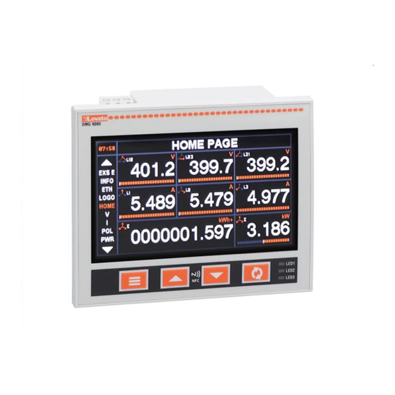
Description
Details on the three-phase digital power analyzer, panel mounting, and display specifications.
Front Panel Operations
Frontal Keys and LEDs Functions
Explains the role of front panel buttons and programmable LEDs for status indication.
Measurement Display Navigation
Describes how to navigate measurement pages, sub-pages, and view data.
Data Visualization and Logging
Waveform and Harmonics Pages
Displays harmonic content (spectrum) and waveform periods for electrical quantities.
Trend Pages
Shows changes in time domain for selected measurements like voltage, current, and power.
Event Log
Records events for anomaly detection and plant behavior tracking.
System Expansion and Connectivity
Expandability
Details on adding EXP series modules to enhance analyzer functionality.
Communication Channels
Explains built-in and expandable communication ports (RS485, Ethernet).
Digital and Analog I/O
Covers digital and analog inputs/outputs associated with expansion modules.
Advanced System Features
PLC Logic
Enables simple automations using timers, alarms, and digital inputs via Ladder programming.
Easy Branch System
Multi-circuit measuring system for monitoring multiple loads efficiently.
Web Server Functionality
Allows remote access to analyzer data and settings via a web browser.
Data Management and Quality
Data Log
Records date, time, and samples of selected measurements in a data table.
Energy Quality Monitoring (DMG9000)
Checks voltage and frequency quality against EN 50160 standards.
Access Control and Setup
Password Access
Manages access levels to setting menus, commands, and remote connections via password.
Parameter Setup
Guide to accessing and navigating the setup menu and its parameters.
General and Utility Parameter Settings
General Parameters (M01)
Covers CT/VT settings, voltage, frequency, connection type, and reactive power calculation.
Utility Functions (M02)
Includes settings for language, display themes, and backlight intensity.
Password and Integration Parameters
Password Settings (M03)
Enables and configures password access levels for security.
Integration Parameters (M04)
Defines integration modes and time settings for power, current, and voltage measurements.
Counter and Trend Graph Settings
Hour Counter Settings (M05)
Configures general and partial hour counters linked to internal variables or events.
Trend Graph Settings (M06)
Sets up data sources, load numbers, and display scaling for trend graphs.
Communication and Limit Settings
Communication Settings (M07)
Configures serial node address, speed, protocol, IP settings, and port functions.
Limit Thresholds (M08)
Defines thresholds for measurements, including upper/lower limits and hysteresis.
Alarm and Counter Configuration
Alarm Settings (M09)
Configures alarm sources, channels, priority, and custom text messages.
Counter Settings (M10)
Sets up counter sources, channels, multipliers, dividers, and descriptions.
Pulse and LED Indicator Settings
Pulse Output Configuration (M11)
Configures pulse output source, number of pulses, duration, and CT position.
LED Indicator Functions (M12)
Assigns functions to front panel LEDs for status indication.
Digital I/O Configuration
Digital Inputs (M13)
Configures input functions, channel numbers, contact types, and delays.
Digital Outputs (M14)
Configures output functions, channel numbers, and output types.
Analog I/O and NFC Setup
Analog Inputs (M15)
Configures analog input types, scale values, multipliers, and descriptions.
Analog Outputs (M16)
Configures analog output types, reference measures, and scale values.
User Pages, Timers, and NFC
User Pages (M17)
Allows customization of display pages by selecting specific measurements.
Timer Configuration (M18)
Sets up timers based on sources, channels, and delays.
Energy Quality and Branch System Configuration
Energy Quality Configuration (M19)
Sets thresholds for voltage, frequency, and harmonics for energy quality analysis.
Easy Branch System Setup (M20)
Configures load types, CT/VT settings, and voltage sources for the Easy Branch system.
Interface and Connectivity Options
NFC Parameter Setup
Configure and modify parameters wirelessly using the LOVATO NFC App.
Infrared Optical Port
Connects to CX01/CX02 devices for configuration, diagnostics, and firmware updates.
System Commands and Testing
Commands List
Provides a list of executable commands for device control and reset operations.
Wiring Test
Checks the correct installation of the power analyzer by verifying voltages and phase sequence.
Physical Installation and Diagrams
Mechanical Dimensions and Terminals
Details physical layout, dimensions, and terminal positions for various DMG models.
Wiring Diagrams
Illustrates electrical connection diagrams for single-phase and three-phase systems.
Technical Specifications
Technical Characteristics
Lists general technical specifications like auxiliary supply, voltage, frequency, and power consumption.
Measurement Accuracy
Specifies accuracy classes for various measurements like voltage, current, power, and energy.
Need help?
Do you have a question about the DMG7500 and is the answer not in the manual?
Questions and answers