Advertisement
WARNING!
Carefully read the manual before the installation or use.
This equipment is to be installed by qualified personnel, complying to current standards, to
avoid damages or safety hazards.
Before any maintenance operation on the device, remove all the voltages from measuring and supply inputs and
short- circuit the CT input terminals.
The manufacturer cannot be held responsible for electrical safety in case of improper use of the equipment.
Products illustrated herein are subject to alteration and changes without prior notice. Technical data and
descriptions in the documentation are accurate, to the best of our knowledge, but no liabilities for errors, omissions
or contingencies arising there from are accepted.
A circuit breaker must be included in the electrical installation of the building. It must be installed close by the
equipment and within easy reach of the operator. It must be marked as the disconnecting device of the
equipment: IEC /EN 61010-1 § 6.11.3.1
Clean the device with a soft dry cloth; do not use abrasives, liquid detergents or solvents.
ATTENTION!
Lire attentivement le manuel avant toute utilisation et installation.
Ces appareils doivent être installés par un personnel qualifié, conformément aux normes en vigueur
en matière d'installations, afin d'éviter de causer des dommages à des personnes ou choses.
Avant toute intervention sur l'instrument, mettre les entrées de mesure et d'alimentation hors tension et court-
circuiter les transformateurs de courant.
Le constructeur n'assume aucune responsabilité quant à la sécurité électrique en cas d'utilisation impropre
du dispositif.
Les produits décrits dans ce document sont susceptibles d'évoluer ou de subir des modifications à n'importe
quel moment. Les descriptions et caractéristiques techniques du catalogue ne peuvent donc avoir aucune
valeur contractuelle.
Un interrupteur ou disjoncteur doit être inclus dans l'installation électrique du bâtiment. Celui-ci doit se trouver
tout près de l'appareil et l'opérateur doit pouvoir y accéder facilement. Il doit être marqué comme le dispositif
d'interruption de l'appareil : IEC/ EN 61010-1 § 6.11.3.1.
Nettoyer l'appareil avec un chiffon doux, ne pas utiliser de produits abrasifs, détergents liquides ou solvants.
ACHTUNG!
Dieses Handbuch vor Gebrauch und Installation aufmerksam lesen.
Zur Vermeidung von Personen- und Sachschäden dürfen diese Geräte nur von qualifiziertem
Fachpersonal und unter Befolgung der einschlägigen Vorschriften installiert werden.
Vor jedem Eingriff am Instrument die Spannungszufuhr zu den Messeingängen trennen und die Stromwandler
kurzschlie en.
Bei zweckwidrigem Gebrauch der Vorrichtung übernimmt der Hersteller keine Haftung für die elektrische Sicherheit.
Die in dieser Broschüre beschriebenen Produkte können jederzeit weiterentwickelt und geändert werden. Die im
Katalog enthaltenen Beschreibungen und Daten sind daher unverbindlich und ohne Gewähr.
In die elektrische Anlage des Gebäudes ist ein Ausschalter oder Trennschalter einzubauen. Dieser muss sich in
unmittelbarer Nähe des Geräts befinden und vom Bediener leicht zugänglich sein. Er muss als Trennvorrichtung für
das Gerät gekennzeichnet sein: IEC/ EN 61010-1 § 6.11.3.1.
Das Gerät mit einem weichen Tuch reinigen, keine Scheuermittel, Flüssigreiniger oder Lösungsmittel verwenden.
ADVERTENCIA
Leer atentamente el manual antes de instalar y utilizar el regulador.
Este dispositivo debe ser instalado por personal cualificado conforme a la normativa de
instalación vigente a fin de evitar daños personales o materiales.
Antes de realizar cualquier operación en el dispositivo, desconectar la corriente de las entradas de
alimentación y medida, y cortocircuitar los transformadores de corriente.
El fabricante no se responsabilizará de la seguridad eléctrica en caso de que el dispositivo no se utilice de
forma adecuada.
Los productos descritos en este documento se pueden actualizar o modificar en cualquier momento. Por
consiguiente, las descripciones y los datos técnicos aquí contenidos no tienen valor contractual.
La instalación eléctrica del edificio debe disponer de un interruptor o disyuntor. Éste debe encontrarse cerca del
dispositivo, en un lugar al que el usuario pueda acceder con facilidad. Además, debe llevar el mismo marcado que
el interruptor del dispositivo (IEC/ EN 61010-1 § 6.11.3.1).
Limpiar el dispositivo con un trapo suave; no utilizar productos abrasivos, detergentes líquidos ni disolventes.
UPOZORN NÍ
Návod se pozorn pro t te, než za nete regulátor instalovat a používat.
Tato za ízení smí instalovat kvalifikovaní pracovníci v souladu s platnými p edpisy a normami
pro p edcházení úraz osob i poškození v cí.
P ed jakýmkoli zásahem do p ístroje odpojte m icí a napájecí vstupy od nap tí a zkratujte transformátory proudu.
Výrobce nenese odpov dnost za elektrickou bezpe nost v p ípad nevhodného používání regulátoru.
Výrobky popsané v tomto dokumentu mohou kdykoli projít úpravami i dalším vývojem. Popisy a údaje uvedené v
katalogu nemají proto žádnou smluvní hodnotu.
Spína i odpojova je nutno zabudovat do elektrického rozvodu v budov . Musejí být nainstalované v t sné
blízkosti p ístroje a snadno dostupné pracovníku obsluhy. Je nutno ho ozna it jako vypínací za ízení p ístroje:
IEC/ EN 61010-1 § 6.11.3.1.
P ístroj ist te m kkou ut rkou, nepoužívejte abrazivní produkty, tekutá istidla i rozpoušt dla.
AVERTIZARE!
Citi i cu aten ie manualul înainte de instalare sau utilizare.
Acest echipament va fi instalat de personal calificat, în conformitate cu standardele actuale,
pentru a evita deterior ri sau pericolele.
Înainte de efectuarea oric rei opera iuni de între inere asupra dispozitivului, îndep rta i toate tensiunile de la intr rile
de m surare
i de alimentare i scurtcircuita i bornele de intrare CT.
Produc torul nu poate fi considerat responsabil pentru siguran a electric în caz de utilizare incorect a
echipamentului.
Produsele ilustrate în prezentul sunt supuse modific rilor i schimb rilor f r notificare anterioar . Datele tehnice
i descrierile din documenta ie sunt precise, în m sura cuno tin elor noastre, dar nu se accept nicio r spundere
pentru erorile, omiterile sau evenimentele neprev zute care apar ca urmare a acestora.
Trebuie inclus un disjunctor în instala ia electric a cl dirii. Acesta trebuie instalat aproape de echipament i
într-o zon u or accesibil operatorului. Acesta trebuie marcat ca fiind dispozitivul de deconectare al
echipamentului: IEC/EN 61010-1 § 6.11.3.1.
Cur a i instrumentul cu un material textil moale i uscat; nu utiliza i substan e abrazive, detergen i lichizi sau
solven i.
POWER ANALYZERS
Instruction manual
ANALIZATORY PARAMETRÓW SIECI
Instrukcja obs ugi
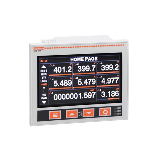
DMG7000-7500-8000-9000
ATTENZIONE!
Leggere attentamente il manuale prima dell'utilizzo e l'installazione.
Questi apparecchi devono essere installati da personale qualificato, nel rispetto delle vigenti
normative impiantistiche, allo scopo di evitare danni a persone o cose.
Prima di qualsiasi intervento sullo strumento, togliere tensione dagli ingressi di misura e di alimentazione
e cortocircuitare i trasformatori di corrente.
Il costruttore non si assume responsabilità in merito alla sicurezza elettrica in caso di utilizzo improprio del dispositivo.
I prodotti descritti in questo documento sono suscettibili in qualsiasi momento di evoluzioni o di modifiche. Le
descrizioni ed i dati a catalogo non possono pertanto avere alcun valore contrattuale.
Un interruttore o disgiuntore va compreso nell'impianto elettrico dell'edificio. Esso deve trovarsi in stretta vicinanza
dell'apparecchio ed essere facilmente raggiungibile da parte dell'operatore. Deve essere marchiato come il
dispositivo di interruzione dell'apparecchio: IEC/ EN 61010-1 § 6.11.3.1.
Pulire l'apparecchio con panno morbido, non usare prodotti abrasivi, detergenti liquidi o solventi.
UWAGA!
Przed u yciem i instalacj urz dzenia nale y uwa nie przeczyta niniejsz instrukcj .
W celu unikni cia obra e osób lub uszkodzenia mienia tego typu urz dzenia musz by
instalowane przez wykwalifikowany personel, zgodnie z obowi zuj cymi przepisami.
Przed rozpocz ciem jakichkolwiek prac na urz dzeniu nale y od czy napi cie od wej pomiarowych i
zasilania oraz zewrze zaciski przek adnika pr dowego.
Producent nie przyjmuje na siebie odpowiedzialno ci za bezpiecze stwo elektryczne w przypadku
niew a ciwego u ytkowania urz dzenia.
Produkty opisane w niniejszym dokumencie mog by w ka dej chwili udoskonalone lub zmodyfikowane.
Opisy oraz dane katalogowe nie mog mie w zwi zku z tym adnej warto ci umownej.
W instalacji elektrycznej budynku nale y uwzgl dni prze cznik lub wy cznik automatyczny. Powinien on
znajdowa si w bliskim s siedztwie urz dzenia i by atwo osi galny przez operatora. Musi by oznaczony jako
urz dzenie s u ce do wy czania urz dzenia: IEC/ EN 61010-1 § 6.11.3.1.
Urz dzenie nale y czy ci mi kk szmatk , nie stosowa rodkow ciernych, p ynnych detergentow lub rozpuszczalnikow.
!
.
( ).
.
,
.
,
D KKAT!
Montaj ve kullanımdan önce bu el kitabını dikkatlice okuyunuz.
Bu aparatlar ki ilere veya nesnelere zarar verme ihtimaline kar ı yürürlükte olan sistem kurma
normlarına göre kalifiye personel tarafından monte edilmelidirler
Aparata (cihaz) herhangi bir müdahalede bulunmadan önce ölçüm giri lerindeki gerilimi kesip akım
transformatörlerinede kısa devre yaptırınız.
Üretici aparatın hatalı kullanımından kaynaklanan elektriksel güvenli e ait sorumluluk kabul etmez.
Bu dokümanda tarif edilen ürünler her an evrimlere veya de i imlere açıktır. Bu sebeple katalogdaki tarif ve
de erler herhangi bir ba layıcı de eri haiz de ildir.
Binanın elektrik sisteminde bir anahtar veya alter bulunmalıdır. Bu anahtar veya alter operatörün kolaylıkla
ula abilece i yakın bir yerde olmalıdır. Aparatı (cihaz) devreden çıkartma görevi yapan bu anahtar veya alterin
markası: IEC/ EN 61010-1 § 6.11.3.1.
Aparatı (cihaz) sıvı deterjan veya solvent kullanarak yumu ak bir bez ile siliniz a ındırıcı temizlik ürünleri kullanmayınız
,
.
,
,
,
.
: IEC /EN 61010-1 § 6.11.3.1.
,
.
Advertisement
Table of Contents

Related Manuals for Lovato DMG7000


Summary of Contents for Lovato DMG7000
- Page 1 POWER ANALYZERS Instruction manual ANALIZATORY PARAMETRÓW SIECI Instrukcja obs ugi DMG7000-7500-8000-9000 WARNING! ATTENZIONE! Carefully read the manual before the installation or use. Leggere attentamente il manuale prima dell’utilizzo e l’installazione. This equipment is to be installed by qualified personnel, complying to current standards, to Questi apparecchi devono essere installati da personale qualificato, nel rispetto delle vigenti avoid damages or safety hazards.
- Page 2 Portuguese, Czech, Polish, Russian, Chinese); niemieckim, portugalskim, czeskim, polskim, rosyjskim i chi skim); NFC access to be used with the Lovato NFC app available for Android and iOS devices; dost p NFC w przypadku korzystania z aplikacji Lovato NFC dost pnej na urz dzenia optical port at back of the power analyzer compatible with CX01 (USB) and CX02 (Wi-Fi) z systemami Android i iOS;...
-
Page 3: Measurement Display
FRONTAL KEYS AND LEDS FUNCTIONS FUNKCJE PRZYCISKÓW I WSKA NIKÓW LED NA PANELU PRZEDNIM User programmable LEDs 3 wska niki LED z mo liwo ci Access to and exit from setup and measurement menus zaprogramowania przez u ytkownika Wchodzenie do menu ustawie i pomiarów oraz wychodzenie z niego Selection confirmation and sub-pages browsing Potwierdzanie wyborów i przewijanie podstron... - Page 4 POWER FACTOR PF L1 PF L2 PF L3 cos L1 cos L2 cos L3 WSPÓ CZYNNIK MOCY ENERGY TOT SYS (L1+L2+L3) PAR SYS (L1+L2+L3) ENERGIA kWh+ kWh- kvarh+ kvarh- kVAh kWh+ kWh- kvarh+ kvarh- kVAh TOT SYS (L1+L2+L3) TOT L1 kWh+ kWh- kvarh+...
- Page 5 SZCZEGÓ Y DOT. WYJ (z zainstalowanym modu em rozszerze ) COUNTERS (P10.n.01) CNT 1 … CNT 8 LICZNIKI (P10.n.01) DATE / TIME DATA / GODZINA Serial Backup SYSTEM INFO Model number status PLC status NFC status INFO INFORAMCJE O SW rev. HW rev.
- Page 6 WAVEFORM AND HARMONICS PAGES STRONY DOT. PRZEBIEGÓW FALI I HARMONICZNYCH DMGs provide the harmonic analysis up to the 63rd order (7th order if the operating frequency is W modelach DMG dost pna jest analiza harmonicznych do 63 w kolejno ci (do 7 w kolejno ci, je li 400Hz) of the phase-to-phase voltages, phase-to-neutral voltages, phase and neutral currents.
- Page 7 RS485 port of a DMG to which other instruments equipped with RS485 serial port. i portem RS485 w DMG, do którego pod czane s urz dzenia wyposa one w port szeregowy RS485. MODEL BUILT-IN COMMUNICATION PORTS MODEL WBUDOWANE PORTY KOMUNIKACJI DMG7000 DMG7000 DMG7500 RS485 (COM1) DMG7500 RS485 (COM1)
- Page 8 Rozdzielnice elektryczne w centrach handlowych lub na wydzia ach produkcyjnych where to install the EASY BRANCH system by LOVATO Electric. to idealne miejsca do zainstalowania systemu EASY BRANCH firmy LOVATO Electric. Benefits: Zalety: reduction of wiring times;...
- Page 9 Name of branch points setup Ustawienia nazw punktów Easy branch veform charts esy przebiegu fali Parameter file man Zarz dzanie p z parametra...
-
Page 10: Rejestr Danych
DATA LOG REJESTR DANYCH The data log is a data table which records in each row the date, time and relevant samples of the Rejestr danych jest to tabela z danymi, która w ka dym swoim wierszu rejestruje informacje dotycz ce measurements selected by the user. -
Page 11: Password Access
PASSWORD ACCESS HAS O DOST PU The password enables access to the setting menu, the commands menu or remote connection via Has o umo liwia dost p do menu ustawie , do menu komend lub dost p zdalny poprzez porty communication ports. - Page 12 Timers Timery Energy quality (DMG9000) Jako energii (DMG9000) Easy branch (DMG7500 – DMG8000 – Easy branch (DMG7500 – DMG8000 – DMG9000) DMG9000) Keys : move the selection to the different menu or parameter items, increase or decrease the Przyciski : pozwalaj na dokonywanie wyboru spo ród ró nych pozycji menu lub wybór values;...
- Page 13 Light 4 Jasny 4 Dark 5 Ciemny 5 Light 5 Jasny 5 Dark 6 Ciemny 6 Light 6 Jasny 6 P02.03 Backlight high intensity 0-100 P02.03 Intensywno pod wietlania 0-100 wy wietlacza wysoka P02.04 Backlight low intensity 0-50 P02.04 Intensywno pod wietlania 0-50 wy wietlacza niska...
- Page 14 dla punktów pomiaru EASY Branch. P04.07 – AVG (average) measurement integration time for the currents of the EASY Branch measurement points. P04.07 – Czas integracji pomiarów AVG ( rednia) w przypadku pr dów punktów pomiaru EASY Branch. M05 – HOUR COUNTERS Default Range M05 –...
- Page 15 7 bit-odd 7 bit-odd 7 bit-even 7 bit-even P07.n.04 Stop bit P07.n.04 Bit stop P07.n.05 Protocol Modbus RTU Modbus RTU P07.n.05 Protokó Modbus RTU Modbus RTU Modbus ASCII Modbus ASCII Modbus TCP Modbus TCP P07.n.06 IP address 192.168.1.1 000.000.000.000 P07.n.06 Adres IP 192.168.1.1 000.000.000.000...
- Page 16 M09 - ALARMS (ALAn, n=1...40) Default Range M09 – ALARMY (ALAn, n=1...40) Domy lnie Zakres P09.n.01 Alarm source OFF-LIMx-INPx-PLCx- P09.n.01 ród o alarmu OFF-LIMx-INPx-PLCx- TIMx TIMx P09.n.02 Channel number (x) 1-40 P09.n.02 Numer kana u (x) 1-40 P09.n.03 Latch OFF-ON P09.n.03 Pami OFF-ON...
- Page 17 P13.n.05 Falling delay 0.05 0.00 – 300.00 P13.n.05 Opó nienie odwzbudzenia 0.05 0.00 – 300.00 P13.n.01 – Input function. P13.n.01 – Funkcja wej cia. OFF: input disabled. OFF: wej cie nieaktywne. ON: input enabled, used as a source for other functions. ON: wej cie aktywne, u ywane jako ród o dla innych funkcji.
- Page 18 P16.n.03 Source MAIN MAIN P16.n.03 ród o MAIN MAIN BRN01…32 BRN01…32 P16.n.04 Load number TOT-1-2-3 P16.n.04 Wybór obci enia TOT-1-2-3 P16.n.05 Channel 1-40 P16.n.05 Kana OFF / 1-40 P16.n.06 Starting scale value -9999 – +9999 P16.n.06 Warto pocz tku skali -9999 –...
- Page 19 With CX02 it is possible to connect with the LOVATO Electric SAM1 app that can be downloaded for W przypadku CX02 mo liwe jest po czenie z aplikacj LOVATO Electric SAM1, któr mo na pobra free from the Google Play Store and App Store for Android and iOS smart devices for: nieodp atnie ze sklepów Google Play Store i App Store na urz dzenia mobilne z systemami Android...
- Page 20 SLOT 2 GNIAZDO NR 2 COMMANDS KOMENDY Starting from the measurement reading pages, press the button to access the menu and then select Na stronach odczytu pomiarów nacisn przycisk i wej do menu, a nast pnie wybra ikon the "command" icon to access the commands list. If the icon is gray, the password is required „komendy”, aby wej do listy komend.
-
Page 21: Wiring Diagrams
MECHANICAL DIMENSIONS AND TERMINALS POSITION WYMIARY MECHANICZNE I ROZMIESZCZENIE ZACISKÓW DMG9000 DMG8000 DMG7500 DMG7000 WIRING DIAGRAMS SCHEMATY ELEKTRYCZNE (V4 and I4 available on DMG9000 only) (V4 i I4 s dost pne tylko w DMG9000) 3-ph with or without neutral – Trójfazowy z przewodem neutralnym lub bez... -
Page 22: Technical Characteristics
Wej cia napi cia Input type 3-phase + neutral Typ wej cia 3 F + N (DMG7000 – DMG7500 – DMG8000) (DMG7000 – DMG7500 – DMG8000) Input type 3-phase + neutral + earth Typ wej cia 3 F + N + uziemienie (PE) - Page 23 Measurement accuracy Dok adno pomiaru Reference temperature +23°C ± 2°C Temperatura odniesienia + 23°C ± 2°C Phase – neutral voltage Class 0.2 (IEC/EN/BS 61557-12), V: 50 – 480 V~ Napi cie fazowe Klasa 0,2 (IEC/EN/BS 61557-12), V: 50 – 480 V~ Phase –...
Need help?
Do you have a question about the DMG7000 and is the answer not in the manual?
Questions and answers