Table of Contents
Advertisement
Quick Links
Advertisement
Table of Contents

Related Manuals for Temposonics EP


Summary of Contents for Temposonics EP
- Page 1 Operation Manual E-Series IO-Link Magnetostrictive Linear Position Sensors...
-
Page 2: Table Of Contents
3.6 Approvals ........................................9 3.7 Scope of delivery ....................................... 9 4. Product description and commissioning ........................10 4.1 Functionality and system design ................................10 4.2 Styles and installation of Temposonics EH ............................. 11 ® 4.3 Styles and installation of Temposonics EP/EL ............................13 ®... -
Page 3: Introduction
The sensor will not work Wrong sensor connection properly or can be damaged Before starting the operation of Temposonics position sensors, read Operate the sensor out of the No signal output – this documentation thoroughly and follow the safety information. -
Page 4: Installation, Commissioning And Operation
The Temposonics obligation is limited to repair or replacement of any If danger of injury to persons or of damage to operating equipment defective part of the unit. No warranty can be provided for defects... -
Page 5: Identification
Temposonics E-Series IO-Link ® Operation Manual 3. Identification 3.1 Order code of Temposonics ® optional d Connection type d Connection type a Sensor model 4 M12 male connector (4 pin) 4 M12 male connector (4 pin) H Rod e Operating voltage... -
Page 6: Order Code Of Temposonics ® Ep/El
Temposonics E-Series IO-Link ® Operation Manual 3.2 Order code of Temposonics EP/EL ® optional a Sensor model d Connection type d Connection type P Ultra low profi le 4 M12 male connector (4 pin) 4 M12 male connector (4 pin) -
Page 7: Order Code Of Temposonics ® Ep2
Temposonics E-Series IO-Link ® Operation Manual 3.3 Order code of Temposonics ® a Sensor model c Connection type 2 Smooth profi le 4 M12 (4 pin) male connector b Stroke length Operating voltage X M 0050…2540 mm +24 VDC (±25 %) -
Page 8: Order Code Of Temposonics ® Er
Temposonics E-Series IO-Link ® Operation Manual 3.4 Order code of Temposonics ® a Sensor model R Aluminum cylinder with a guided driving rod b Design M Inside thread M6 at end of rod (For metric stroke length measurement) Inside thread ¼"-28 UNF at end of rod... -
Page 9: Nameplate
Serial number S/N: 70008887 1 mounting clamp for each 500 mm (20 in.) additional stroke length ER (aluminum cylinder with a guided driving rod sensor): Fig. 1: Example of nameplate of an E-Series EH sensor • Sensor 3.6 Approvals • CE certified •... -
Page 10: Product Description And Commissioning
• The external position magnet is a permanent magnet. Mounted on the mobile machine part, it travels along the sensor rod or profile The absolute, linear position sensors provided by Temposonics rely on the company’s proprietary magnetostrictive technology, which can and triggers the measurement through the sensor rod wall. -
Page 11: Styles And Installation Of Temposonics ® Eh
Temposonics E-Series IO-Link ® Operation Manual 4.2 Styles and installation of Temposonics ® EH with threaded fl ange M18×1.5-6g or ¾"-16 UNF-3A Stroke length Sensor electronics housing Null zone Dead zone 50…2540 63.5 (2…100) (0.51) (1.89) (2.01) (2.5) 4 pin A/F 34 Flange »K«, »M«, »W«: M18×1.5-6g... - Page 12 Temposonics E-Series IO-Link ® Operation Manual Notice for metric threaded fl anges Thread Z° ×P) +0.1 +0.4 ±1° EH-K (Ø 7 mm rod) M18×1.5-6g 55 ≥ 10 24.5 19.8 28.5 26 15° EH-M/-W (Ø 10 mm rod) M18×1.5-6g 55 ≥ 13 24.5 19.8 28.5...
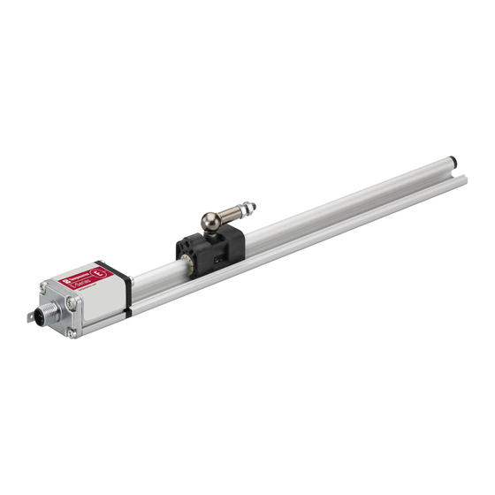
- Page 13 Block magnet L: 32.5 (1.28) Controlling design dimensions are in millimeters and measurements in ( ) are in inches Fig. 8: E-Series EP and EL with magnet slider Installation of EP/EL The position sensor can be installed in any position. Normally, the sensor is firmly installed and the position magnet is fastened to the mobile machine part.
-
Page 14: Styles And Installation Of Temposonics ® Ep2
Temposonics E-Series IO-Link ® Operation Manual 4.4 Styles and installation of Temposonics ® Null zone Stroke length Dead zone 50…2540 (2.87) (2…100) (2.87) Mounting support 3 ± 2 (0.12 ± 0.08) 8 ± 2 (0.31 ± 0.08) (0.51) 4 pin 14.6... -
Page 15: Styles And Installation Of Temposonics ® Er
Temposonics E-Series IO-Link ® Operation Manual 4.5 Styles and installation of Temposonics ® (0.12) Stroke length 35.5 50…1500 132.5 + stroke length (1.40) 17.8 M12×1 (5.22 + stroke length) (2…60) (0.7) 4 pin Optional: Optional: (1.97) Adjustable Adjustable Optional: rod end M6 /... -
Page 16: Magnet Installation
Temposonics E-Series IO-Link ® Operation Manual 4.6 Magnet installation Magnet Typical sensors Benefi ts Ring magnets Rod model • Rotationally symmetrical Air gap: 3 ±2 8 ±2 (EH) magnetic fi eld (0.12 ±0.08) (0.31 ±0.08) Sensing element Block magnet U-magnets Profi... - Page 17 Start position End position 48.5 (1.91) 66 (2.6) EH with block magnets ≥ 75 (≥ 3) E-Series EP with magnet slider “S”, “N”, “V”, “G” Start position End position 19 (0.75) 84 (3.3) EP with magnet sliders ≥ 75 (≥ 3)
-
Page 18: Electrical Connections
EP, EL, EP2 and ER via ground lug as shown in Fig. 23. The sensor type EH is grounded via thread. */ The use of shielded cables is a recommendation of Temposonics to afford a better protection against signal disturbances... -
Page 19: Frequently Ordered Accessories
Temposonics E-Series IO-Link ® Operation Manual 4.8 Frequently ordered accessories – Additional options available in our Accessories Guide 551 444 Position magnets Ø 32.8 Ø 32.8 (Ø 1.29) Ø 25.4 Ø 4.3 (Ø 1.29) Ø 17.4 (Ø 1) Ø 4.3 (Ø... - Page 20 Temposonics E-Series IO-Link ® Operation Manual Cable connectors Cables (2.25) (2.09) Ø 20 (Ø 0.79) M12 A-coded female connector M12 A-coded female connector Cable with M12 A-coded female Cable with M12 A-coded female (4 pin/5 pin), straight (5 pin), angled connector (5 pin), straight –...
-
Page 21: Operation
Please choose the appropriate IODD file for your E-Series IO-Link. The E-Series IO-Link can be connected to IO-Link masters with a maximum master cycle time of 20 ms. Contact us if you use the E-Series IO-Link in an application with a master cycle time > 20 ms. -
Page 22: Identification Parameter
Vendor name string Temposonics GmbH and Co. KG 0x11 0x00 Vendor text string www.temposonics.com 0x12 0x00 Product name string E-Series IO-Link (short)/E-Series IO-Link (long)/E-Series IO-Link (multi-magnet) 0x13 0x00 Product ID string Ex-x-xxxxx-D44-1-K/Ex-x-xxxxx-D44-1-K-x-Zxx 0x14 0x00 Product text string Temposonics E-Series 0x15... -
Page 23: Measuring Parameter
Temposonics E-Series IO-Link ® Operation Manual 5.3 Measuring parameter These parameters allow the sensor to be adapted to the application. The resolution, a filter of the measured value and the measuring direction can all be configured. Index Subindex Parameter Data type... - Page 24 Temposonics E-Series IO-Link ® Operation Manual Teach offset for advanced single-position measurement and multi-position measurement • Select the magnet to be used for teaching the offset via the index 0x82 subindex 0x01. • Move magnet to desired position. • Enter the value to be output at this point via index 0x82 subindex 0x02.
-
Page 25: Switch Points
Temposonics E-Series IO-Link ® Operation Manual 5.5 Switch points The digital output of the sensor on pin 2 (DI/DQ) can be configured as a switch point (see "4.7 Electrical connections" on page 18). This switch point is output in parallel to the position value. The switch point respectively the switch points and the switch logic can be adjusted. -
Page 26: Set Measurement Range
Temposonics E-Series IO-Link ® Operation Manual Switch point Deactivate (default) Single point mode Switch logic: Non-inverted Switch logic: Inverted Switch point 1 Switch point 1 Window mode Switch logic: Non-inverted Switch logic: Inverted Switch point 1 Switch point 2 Switch point 1 Switch point 2 Fig. 27: Functionality of switch point parameters... -
Page 27: Error/Warning Messages
No magnet/Too few magnets (for multi-position measurement only) 0x8CA3 (Dis)appear Warning Over range of measurement 0x8CA4 (Dis)appear Warning Under range of measurement Table 9: Error codes specified by Temposonics Code Message 0x8011 Index not available 0x8012 Sub-index not available 0x8022 Service temporarily not available – local control... -
Page 28: Data Storage Mechanism
5.8 Data storage mechanism The data storage mechanism enables to save the parameters of an IO-Link device on a connected IO-Link master. Table 11 lists the parameters of the E-Series IO-Link which are buffered by the data storage mechanism: Index... -
Page 29: Device Access Lock
See chapter "5. Operation" on page 21. 7.2 Maintenance The sensor is maintenance-free. 7.3 Repair Repairs of the sensor may be performed only by Temposonics or a repair facility explicitly authorized by Temposonics. 7.4 List of spare parts No spare parts are available for this sensor. -
Page 30: Technical Data
Temposonics E-Series IO-Link ® Operation Manual 8. Technical data 8.1 Technical data of Temposonics ® Output Interface Digital Transmission protocol IO-Link V1.1 Data format Standard single-postion measurement: 32 bit signed (position in μm) Advancded single-position measurement and multi-position measurement: 8 × 32 bit signed (position in µm, velocity in µm/s) -
Page 31: Technical Data Of Temposonics ® Ep/El
Temposonics E-Series IO-Link ® Operation Manual 8.2 Technical data of Temposonics EP/EL ® Output Interface Digital Transmission protocol IO-Link V1.1 Data format Standard single-postion measurement: 32 bit signed (position in μm) Advancded single-position measurement and multi-position measurement: 8 × 32 bit signed (position in µm, velocity in µm/s) -
Page 32: Technical Data Of Temposonics ® Ep2
Temposonics E-Series IO-Link ® Operation Manual 8.3 Technical data of Temposonics ® Output Interface Digital Transmission protocol IO-Link V1.1 Data format Standard single-postion measurement: 32 bit signed (position in μm) Advancded single-position measurement and multi-position measurement: 8 × 32 bit signed (position in µm, velocity in µm/s) -
Page 33: Technical Data Of Temposonics ® Er
Temposonics E-Series IO-Link ® Operation Manual 8.4 Technical data of Temposonics ® Output Interface Digital Transmission protocol IO-Link V1.1 Data format Standard single-postion measurement: 32 bit signed (position in μm) Advancded single-position measurement: 8 × 32 bit signed (position in µm, velocity in µm/s) Data transmission rate COM3 (230.4 kBaud) -
Page 34: Appendix
The sensor has been in contact with the following materials: In the event of suspected penetration of substances into the sensor, Do not specify chemical formulas. consult Temposonics to determine measures to be taken before Please include safety data sheets of the substances, if applicable. shipment. - Page 35 © 2022 Temposonics, LLC – all rights reserved. Temposonics, LLC and Temposonics GmbH & Co. KG are subsidiaries of Amphenol Corporation. Except for any third party marks for which attribution is provided herein, the company names and product names used in this document may be the registered trademarks or unregistered trademarks of Temposonics, LLC or...
Need help?
Do you have a question about the EP and is the answer not in the manual?
Questions and answers