Table of Contents
Advertisement
Quick Links
Advertisement
Table of Contents

Related Manuals for Temposonics GB Series


Summary of Contents for Temposonics GB Series
- Page 1 Operation Manual GB-Series SSI Magnetostriktive Lineare Positionssensoren...
-
Page 2: Table Of Contents
3.3 Approvals ........................................7 3.4 Scope of delivery ......................................7 4. Product description and commissioning ........................7 4.1 Functionality and system design ................................... 7 4.2 Styles and installation of Temposonics ® GB-J / GB-K / GB-N / GB-S ......................8 ®... -
Page 3: Introduction
® 1. The sensor systems of all Temposonics series are intended exclusively for measurement tasks encountered in industrial, commercial and laboratory applications. The sensors are considered as system accessories and must be connected to suitable evaluation electronics, e.g. -
Page 4: Installation, Commissioning And Operation
2.5 Warranty ® The position sensors must be used only in technically safe condition. MTS Sensors grants a warranty period for the Temposonics posi- To maintain this condition and to ensure safe operation, installation, tion sensors and supplied accessories relating to material defects and faults that occur despite correct use in accordance with the intended technical personnel. -
Page 5: Identification
Temposonics ® GB-Series SSI Operation Manual ® rder code Temposonics a Sensor model onnector type esign ousing material stainless steel .43 5 ISI 3 3 , ® cable rod material stainless steel .43 ISI 3 4 ® cable ousing material stainless steel .43 5 ISI 3 3 , rod material stainless steel .43 6... - Page 6 ® Temposonics GB-Series SSI Operation Manual utput Synchronous Serial Interface ata length ox no. 4 25 bit 2 24 bit utput format ox no. 5 inary Resolution ox no. 6 . 5 mm . 1 mm . 5 mm .1 mm .
-
Page 7: Nameplate (Example)
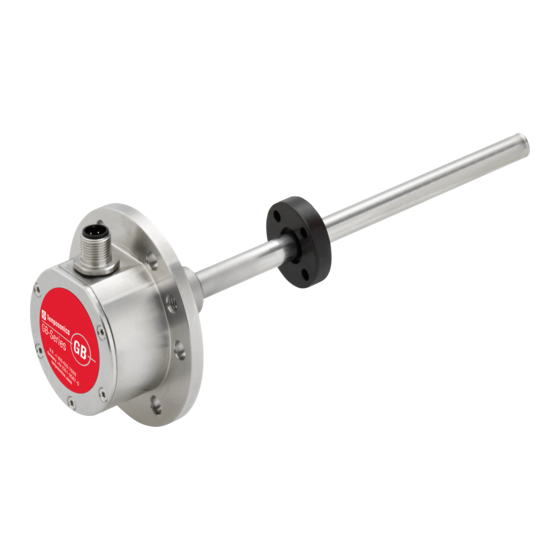
The absolute, linear position sensors provided by MTS Sensors The sensor rod protects the inner sensor element. rely on the company s proprietary Temposonics ® magnetostrictive The sensor electronics housing, a rugged stainless steel... -
Page 8: Styles And Installation Of Temposonics
® Temposonics GB-Series SSI Operation Manual ® 4.2 Styles and installation of Temposonics GB-S (rod sensor with pressure fit flange) GB-S, example With 2 connector Sensor electronics housing ul l zone Stro e length ead zone 2 connector 25 325 63.5... - Page 9 ® Temposonics GB-Series SSI Operation Manual ydraulics sealing Fig. 6. Fastening torque 6 Nm Fig. 4: Sealing via O-ring in the flange undercut Installation of a rod-style sensor in a hydraulic cylinder Fig. 6: Sealing The rod-style version has been developed for direct stroke measure- ment in a hydraulic cylinder.
-
Page 10: Styles And Installation Of Temposonics
® Temposonics GB-Series SSI Operation Manual ® 4.3 Styles and installation of Temposonics GB-T GB-B (rod sensor with threaded flange) Sensor electronics housing Null zone Stroke length Dead zone M12 connector 25…3250 63.5 (1.54) (1.57) (1…128) (2.5) (0.55) Threaded flange »M«: M18×1.5-6g... - Page 11 ® Temposonics GB-Series SSI Operation Manual Base unit xample 6 connector 34.5 NOTICE (1.36) ® GB-B In the event of servicing, the sensor rod with flange remains in the cylinder Fastening torque 50 Nm Position magnet Base unit The sensor electronics housing with sensing element can be replaced Fig.
-
Page 12: Magnet Installation
® Temposonics GB-Series SSI Operation Manual 4.4 agnet instal lation surface. Typical use of magnets The cylinder manufacturer determines the pressure-resistant agnet The position magnet should not grind on the sensor rod. Ring magnets pressure and piston speed. Adhere to the information relating to operating pressure. - Page 13 ® Temposonics GB-Series SSI Operation Manual agnet mounting ith magnetic material cti e measuring range hen using magnetic material the dimensions of Fig. 15 must The technical data of each sensor is checked as well as documented be observed. A. If the position magnet aligns with the drilled piston rod B.
-
Page 14: Change Orientation Of Sensor Electronics Housing
® Temposonics GB-Series SSI Operation Manual 4.5 hange orientation of sensor electronics housing 4.6 Replacement of ase unit The orientation of the sensor electronics housing respectively of shown in Fig. 19. The sensor can be replaced without interrupting the hydraulic circuit. -
Page 15: Electrical Connection
® Temposonics GB-Series SSI Operation Manual lectrical connection onnector iring Connect the sensor directly to the control system, indicator or other system must be ensured by using suitable metal connectors, shielded Signal po er supply cables and grounding. Overvoltages or faulty connections can damage... -
Page 16: Frequently Ordered Accessories
® Temposonics GB-Series SSI Operation Manual re uently ordered accessories Additional options available in our 551 444 osition magnets 1.29 Ø 30.5 Ø 32.8 (Ø 1.2) Ø 25.4 (Ø 1.29) (Ø 1) Ø 4.3 Ø 23.8 (Ø 0.17) (Ø 0.94) Ø... - Page 17 ® Temposonics GB-Series SSI Operation Manual a le connectors ~ 57 ~ 54 (~ 2.24) (~2.13) ~ 60 (~ 2.36) (2.13) Ø 20.5 (0.79) (Ø 0 81) 2 -coded female connector 2 -coded female connector 6 female connector pin , straight...
-
Page 18: Operation
551649. SSI interface TS Sensors programming tools ® ® The interface of Temposonics position sensors corresponds to SSI Temposonics industry standard for absolute encoders. Its displacement value is measurement tasks very easily via the connecting leads without opening the sensor. - Page 19 ® Temposonics GB-Series SSI Operation Manual Programming kit, part no. 254 59 The PC programmer is a hardware converter between sensor and Step 2 Instal l soft are serial PC interface. It can be used for adjusting sensor parameters via computer and the MTS Sensors programming software.
- Page 20 In asynchronous mode the sensor starts measuring and provides the position independent of the P C. Synchron In synchronous mode the output of the Temposonics ® SSI sensor is matched to the data request cycle of the controller. or ard...
-
Page 21: Maintenance And Troubleshooting
Temposonics ® GB-Series SSI Operation Manual 6. aintenanc e and trou leshooting easurement After clicking the Start Read button the current position of the magnet is shown. Click the Stop Read button to stop the measurement rror conditions, trou leshooting... -
Page 22: Technical Data
Temposonics ® GB-Series SSI Operation Manual . Technical data . Technical data GB- GB-S utput Interface Data format inary, gray Programming Programming of set points using optional accessories Measured value Position easurement parameters 5 m minimum Cycle time inearity perating conditions... - Page 23 ® Temposonics GB-Series SSI Operation Manual .2 Technical data GB- GB-T utput Interface Data format inary, gray Programming Programming of set points using optional accessories Measured value Position easurement parameters 5 m minimum Cycle time inearity perating conditions Operating temperature...
-
Page 24: Appendix
. ppendix Safety eclaration Dear Customer, If you return one or several sensors for checking or repair, we need you to sign a safety declaration. The purpose of this declaration is to ensure The sensor has een in contact ith the fol lo ing materials Don t specify chemical formulas. - Page 25 C and Temposonics mb are subsidiaries of Amphenol Corporation. xcept for any third party marks for which attribution is provided herein, the company names and product names used in this document may be the registered trademarks or unregistered trademarks of Temposonics, C or Temposonics mb .
Need help?
Do you have a question about the GB Series and is the answer not in the manual?
Questions and answers