Table of Contents
Advertisement
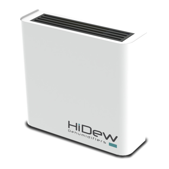
DDS
Dehumidifier for exposed installation swimming pools
DCS
Piped dehumidifier for technical compartment
installation swimming pools
DVS
Vertical dehumidifier for exposed installation swimming
pools
DOS
Horizontal dehumidifier for false ceiling installation
swimming pools
www.hidew.it
info@hidew.it
INSTALLATION, USE AND
MAINTENANCE MANUAL
Advertisement
Table of Contents

Related Manuals for HiDew DCS


Summarization of Contents
Preamble and Safety Information
Manual Usage Guidelines and Safety Symbols
Instructions for reading the manual and explanation of safety symbols.
Responsibility and Service Rules
Manufacturer liability, warranty, service rules, operator obligations, and definitions.
Intended Use and Operating Limits
Specifies intended use for swimming pools and environmental considerations.
Residual Risk Areas Identification
Lists residual risks such as short circuit, fire, explosion, burns, and shearing.
Intervention and Maintenance Guidelines
Emphasizes preventive maintenance, clean workspace, and operator safety precautions.
General Safety Rules and Equipment
Mandates wearing safety equipment and covers fire safety and first aid.
Product Description and Features
Unit Applications and Design
Describes unit use in swimming pools and other environments, and its aesthetic design.
Components and Materials
Details the structure, stainless steel components, and polyester powder coating.
Refrigerant Circuit Specifications
Covers high-quality components, assembly, welding, R410A gas, and compliance.
Ventilation System Details
Describes fans used for DDS, DCS, DVS, and DOS models for corrosion resistance.
Dehumidifier Series and Capacities
Lists DDS, DCS, DVS models with dehumidifying capacities in litres per day.
Operating Limits and Conditions
Defines the operational limits for internal air temperature and humidity.
Unit Dimensions by Model
Provides base, depth, and height dimensions for DDS, DCS, DVS, and DOS series.
Control Functions and Interface
Describes the control system with graphic display, microprocessor, and intuitive interface.
Available Optional Accessories
Lists options like hot water coil, electric heating elements, and remote control kits.
Specific Optional Kits and Features
Covers ducting, plenums, grilles, and installation/filtering options.
Display and Filter Options
Details display mounting, remote options, and circular channel flange kits.
Installation Considerations
Specifies installation locations for DDS, DVS, DOS, and DCS units.
Electrical Circuits Overview
Describes the electrical panel, wiring standards, and low voltage remote controls.
Unit Control System
Control Panel and Display
Overview of the control panel, power board, and elegant display for unit functions.
Button Functions
Details the functions of the ON/OFF, EXIT, MENU, UP, OK, and DOWN keys.
Main Display Page Overview
Explains key usage and describes icons for time, temperature, humidity, and alarms.
User Menu Navigation and Options
Lists the 9 pages of the user menu and how to navigate them.
User Menu: Function Settings
Setting operation mode, desired humidity, temperature, and alarms.
User Menu: Language, Time, and Status
Setting language, date/time, and viewing unit status.
Alarms Menu and Reset
Choosing to display active alarms or reset them, with caution.
Unit Status Information
Displays fan, compressor, valve, heater, and ambient conditions.
Hour Band Menu for Scheduling
Accessing the hour band menu for stand-by, humidity, and temperature programming.
Hour Band Programming Guide and Defaults
Guides through time slot programming and restoring default values.
Other Control Pages
Covers off/stand-by page, software version, and password access.
Technical Data and Performance
DDS and DCS Technical Data Tables
Presents technical specifications for DDS and DCS models 040 to 100.
DDS and DCS Technical Data (160-300)
Provides technical specifications for DDS/DCS models 160 to 300.
DVS Technical Data Tables
Presents technical specifications for DVS models 070 to 230.
DOS Technical Data Tables
Presents technical specifications for DOS models 070 to 230.
Performance Curves for Dehumidification
Graphs showing dehumidification capacity vs. ambient temperature for models 40-100.
Performance Curves: Higher Capacity Models
Graphs showing dehumidification capacity vs. ambient temperature for models 160-300.
Functional Diagram of Refrigerant Circuit
Lists and identifies components within the functional diagram of the refrigerant circuit.
After-Sales Support and Maintenance
Troubleshooting Common Faults
Lists common faults, possible causes, and corrective actions for unit malfunctions.
Ordinary Maintenance Procedures
Instructions for cleaning or replacing air filters for DDS and DCS models.
Air Filter Maintenance: DVS and DOS
Step-by-step guide to removing air filters for DVS models.
Extraordinary Maintenance Procedures
Procedures for cleaning condensate tray and drain pipe for DDS, DCS, DVS, and DOS units.
Maintenance Schedule Table
Table to track and plan maintenance activities over time.
Unit Dismantling and Disposal
Refrigerant and Oil Recovery
Procedures for safe recovery of refrigerant and compressor oil by qualified personnel.
Environmental Protection and Waste Disposal
Guidelines for environmental protection, waste management, and disposal of unit parts.
Installation Procedures and Guidelines
Inspection and Handling During Delivery
Checking for damage upon receipt and safe lifting/transport procedures.
Unit Identification Plate
Explains the identification plate and its data for traceability and maintenance.
Unit Positioning and Space Requirements
General advice for indoor installation, space clearances, and accessibility.
Positioning Space for DVS and DOS
Specifies clearance requirements for DVS and DOS models, including ceiling and drywall.
Hydraulic Connection Guidelines
Mandatory requirements for hydraulic circuit implementation, components, and condensate discharge.
Electrical Connection Procedures
Emphasizes grounding, safe wiring practices, and recommended circuit breaker ratings.
Equipment Fitting for Electrical Connections
Diagrams showing electrical layout and components for DDS/DCS and DVS models.
Terminal Board Connections
Details power supply connections (X1) and alarm/control connections (X3).
Remote Control and Display Connections
Guidance on connecting remote controls, displays, and using remote kit options.
RS485 Modbus Connection
Connecting the Modbus RS485 cable and configuring communication parameters.
First Start-up and Configurations
Pre-start checks, initial start-up procedure, and basic configuration steps.
Flow Rate Calibration for Electronic Fans
Procedure to calibrate fan speed using a channel anemometer for optimal airflow.
Installer Parameter Configuration
Steps to access and modify advanced installer parameters like fan speed and differentials.
Advanced Parameter Settings
Configuring remote device control, defrost parameters, and Modbus settings.
Probe Offset and Parameter Reset
Adjusting probe offsets and restoring unit parameters to default settings.
Dimensional Drawings
DDS Models 40-60 Dimensions
Provides front, side, and top views with dimensions for DDS 40-50-60.
DDS Models 70-100 Dimensions
Provides front, side, and top views with dimensions for DDS 70-90-100.
DDS Models 160-190 Dimensions
Provides front, side, and top views with dimensions for DDS 160-190.
DDS Models 210-300 Dimensions
Provides front, side, and top views with dimensions for DDS 210-230-300.
DCS Models 40-60 Dimensions
Provides views and dimensions for DCS models 40-50-60.
DCS Models 70-100 Dimensions
Provides views and dimensions for DCS models 70-90-100.
DCS Models 160-190 Dimensions
Provides views and dimensions for DCS models 160-190.
DCS Models 210-300 Dimensions
Provides views and dimensions for DCS models 210-230-300.
DVS Models 70-100 Dimensions
Provides views and dimensions for DVS models 70-90-100.
DVS Models 160-230 Dimensions
Provides views and dimensions for DVS models 160-190-210-230.
DOS Models 70-100 Dimensions
Provides views and dimensions for DOS models 70-90-100.
DOS Models 160-230 Dimensions
Provides views and dimensions for DOS models 160-190-210-230.
Need help?
Do you have a question about the DCS and is the answer not in the manual?
Questions and answers