Table of Contents
Advertisement
Quick Links
SPLIT-TYPE, HEAT PUMP AIR CONDITIONERS
TECHNICAL & SERVICE MANUAL
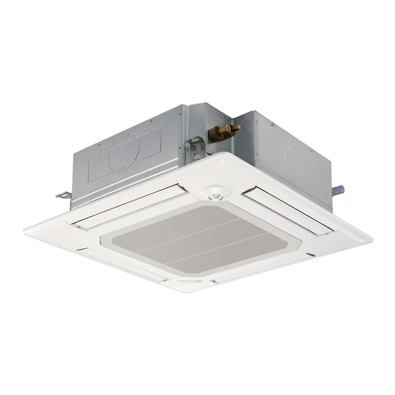
Indoor unit
[Model Name]
PLFY-P15VFM-E
PLFY-P20VFM-E
PLFY-P25VFM-E
PLFY-P32VFM-E
PLFY-P40VFM-E
PLFY-P50VFM-E
Model name
indication
INDOOR UNIT
[Service Ref.]
PLFY-P15VFM-E.TH
PLFY-P20VFM-E.TH
PLFY-P25VFM-E.TH
PLFY-P32VFM-E.TH
PLFY-P40VFM-E.TH
PLFY-P50VFM-E.TH
R410A
Note:
• This manual describes service data
of the indoor units only.
• RoHS compliant products have
<G> mark on spec name plate.
CONTENTS
1. SAFETY PRECAUTION .......................... 2
2. PARTS NAMES AND FUNCTIONS ........ 4
3. SPECIFICATIONS ................................. 12
4. 4-WAY AIR FLOW SYSTEM ................. 14
5. OUTLINES AND DIMENSIONS ............ 16
6. WIRING DIAGRAM ............................... 17
7. REFRIGERANT SYSTEM DIAGRAM ...... 18
8. TROUBLESHOOTING .......................... 19
9. DISASSEMBLY PROCEDURE ............. 27
PARTS CATALOG (OCB601)
October 2015
No. OCH601
Advertisement
Table of Contents

Related Manuals for Mitsubishi Electric CITY MULTI PLFY-P20VFM-E


Summarization of Contents
SAFETY PRECAUTION
CAUTIONS RELATED TO NEW REFRIGERANT
Cautions for units utilizing refrigerant R410A, including handling and tools.
PARTS NAMES AND FUNCTIONS
2-1. Indoor Unit
Identifies and explains the components of the indoor unit.
2-2. WIRED REMOTE CONTROLLER
Details the functions and operations of the PAR-32MAA wired remote controller.
2-3. WIRED REMOTE CONTROLLER
Explains the functions and display of the PAR-21MAA wired remote controller.
SPECIFICATIONS
3-1. SPECIFICATIONS
Lists the technical specifications for cooling, heating, and electrical components.
3-2. ELECTRICAL PARTS SPECIFICATIONS
Details the specifications of various electrical components used in the unit.
4-WAY AIR FLOW SYSTEM
4-1. FRESH AIR INTAKE
Describes the location and method for fresh air intake during installation.
4-2. FRESH AIR INTAKE AMOUNT & STATIC PRESSURE CHARACTERISTICS
Provides data on fresh air intake amount and its relation to static pressure.
4-3. OPERATION IN CONJUNCTION WITH DUCT FAN (Booster fan)
Explains how to connect and operate the unit with an optional duct fan.
4-4. FIXING HORIZONTAL VANE
Details the procedure for fixing the horizontal vane for air outlet direction.
OUTLINES AND DIMENSIONS
Unit Dimensions
Shows detailed dimensions and installation space requirements for the indoor unit.
WIRING DIAGRAM
Model Specific Wiring Diagrams
Provides wiring diagrams for different PLFY series indoor unit models.
REFRIGERANT SYSTEM DIAGRAM
Refrigerant Circuit Overview
Illustrates the refrigerant flow and key components in the system.
TROUBLESHOOTING
8-1. COUNTERMEASURES FOR ERROR DURING TEST RUN
Lists error codes and their corresponding troubleshooting countermeasures.
8-2. HOW TO CHECK THE PARTS
Provides procedures for checking the functionality of key parts using a tester.
8-2-1. Thermistor Characteristic Graph
Displays resistance characteristics of thermistors at different temperatures.
8-2-2. Linear Expansion Valve
Explains the operation and connection of the linear expansion valve.
8-2-3. DC Fan Motor (Fan Motor/Indoor Controller Board)
Details the troubleshooting steps for the DC fan motor and controller board.
8-3. FUNCTION OF DIP SWITCH
Explains the functions and settings of the various DIP switches on the unit.
8-4. TEST POINT DIAGRAM
Shows test points on the indoor controller board for diagnostics.
DISASSEMBLY PROCEDURE
1. Removing the air intake grille and air filter
Step-by-step guide to remove the air intake grille and filter.
2. Removing the panel
Instructions for removing the unit's front panel and corner panels.
3. Removing the electrical parts
Procedure for removing the control box cover and electrical components.
4. Removing the room temperature thermistor (TH21)
Steps to remove the room temperature thermistor.
5. Removing the drain pan
Guide to detach and remove the drain pan.
6. Removing the pipe temperature thermistor/liquid (TH22) and pipe temperature thermistor/gas (TH23)
Steps for removing pipe temperature thermistors.
7. Removing the fan motor (MF)
Instructions for removing the fan motor and turbo fan assembly.
8. Removing the drain pump (DP) and float switch (FS)
Procedure for removing the drain pump and float switch.
9. Removing the heat exchanger
Steps to remove the heat exchanger unit.
Need help?
Do you have a question about the CITY MULTI PLFY-P20VFM-E and is the answer not in the manual?
Questions and answers