Table of Contents
Advertisement
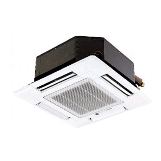
SPLIT-TYPE, HEAT PUMP AIR CONDITIONERS
TECHNICAL & SERVICE MANUAL
Indoor unit
[Model names]
PLFY-P15VCM-E2
PLFY-P20VCM-E2
PLFY-P25VCM-E2
PLFY-P32VCM-E2
PLFY-P40VCM-E2
INDOOR UNIT
Model name
indication
[Service Ref.]
PLFY-P15VCM-E2.TH
PLFY-P15VCM-E2R1.TH
PLFY-P20VCM-E2.TH
PLFY-P20VCM-E2R1.TH
PLFY-P20VCM-E2R2.TH
PLFY-P25VCM-E2.TH
PLFY-P25VCM-E2R1.TH
PLFY-P25VCM-E2R2.TH
PLFY-P32VCM-E2.TH
PLFY-P32VCM-E2R1.TH
PLFY-P32VCM-E2R2.TH
PLFY-P40VCM-E2.TH
PLFY-P40VCM-E2R1.TH
PLFY-P40VCM-E2R2.TH
December 2012
REVISED EDITION-C
R410A
R407C
Revision:
• PLFY-P15VCM-E2R1.TH and
PLFY-P20/25/32/40VCM-E2R2.TH
have been added in REVISED
EDITION-C.
• Some descriptions have been
modified.
• Please void OCH463
REVISED EDITION-B.
Note:
• This manual describes only service
data of the indoor units.
• RoHS compliant products have
<G> mark on spec name plate.
CONTENTS
1. TECHNICAL CHANGES ......................... 2
2. SAFETY PRECAUTION .......................... 2
3. PART NAMES AND FUNCTIONS .......... 6
4. SPECIFICATIONS ................................. 14
5. 4-WAY AIR FLOW SYSTEM ................. 16
6. OUTLINES AND DIMENSIONS ............ 18
7. WIRING DIAGRAM ............................... 19
8. REFRIGERANT SYSTEM DIAGRAM ...... 21
9. TROUBLESHOOTING .......................... 22
10. DISASSEMBLY PROCEDURE ............. 29
PARTS CATALOG (OCB463)
No.OCH463
R22
Advertisement
Table of Contents

Subscribe to Our Youtube Channel
Related Manuals for Mitsubishi Electric PLFY-P15VCM-E2


Summary of Contents for Mitsubishi Electric PLFY-P15VCM-E2
- Page 1 SPLIT-TYPE, HEAT PUMP AIR CONDITIONERS December 2012 No.OCH463 REVISED EDITION-C TECHNICAL & SERVICE MANUAL R410A R407C Indoor unit [Model names] [Service Ref.] Revision: PLFY-P15VCM-E2.TH PLFY-P15VCM-E2 • PLFY-P15VCM-E2R1.TH and PLFY-P15VCM-E2R1.TH PLFY-P20/25/32/40VCM-E2R2.TH have been added in REVISED PLFY-P20VCM-E2.TH PLFY-P20VCM-E2 EDITION-C. • Some descriptions have been PLFY-P20VCM-E2R1.TH modified.
-
Page 2: Technical Changes
TECHNICAL CHANGES PLFY-P15VCM-E2.TH PLFY-P15VCM-E2R1.TH PLFY-P20VCM-E2R1.TH PLFY-P20VCM-E2R2.TH PLFY-P25VCM-E2R1.TH PLFY-P25VCM-E2R2.TH PLFY-P32VCM-E2R1.TH PLFY-P32VCM-E2R2.TH PLFY-P40VCM-E2R1.TH PLFY-P40VCM-E2R2.TH • INDOOR CONTROLLER BOARD has been changed. (S/W version up) PLFY-P20VCM-E2.TH PLFY-P20VCM-E2R1.TH PLFY-P25VCM-E2.TH PLFY-P25VCM-E2R1.TH PLFY-P32VCM-E2.TH PLFY-P32VCM-E2R1.TH PLFY-P40VCM-E2.TH PLFY-P40VCM-E2R1.TH • TURBO FAN has been changed. SAFETY PRECAUTION SAFETY PRECAUTION... -
Page 3: Cautions For Service
[1] Cautions for service · After recovering the all refrigerant in the unit, proceed to working. · Do not release refrigerant in the air. · After completing the repair service, recharge the cycle with the specified amount of liquid refrigerant. [2] Refrigerant recharging (1) Refrigerant recharging process 1Direct charging from the cylinder. - Page 4 Cautions for units utilizing refrigerant R410A Use the following tools specifically designed for Do not use the existing refrigerant piping. use with R410A refrigerant. The old refrigerant and lubricant in the existing piping The following tools are necessary to use R410A refrigerant. contains a large amount of chlorine which may cause the Tools for R410A lubricant deterioration of the new unit.
-
Page 5: Additional Refrigerant Charge
[1] Cautions for service (1) Perform service after recovering the refrigerant left in unit completely. (2) Do not release refrigerant in the air. (3) After completing service, charge the cycle with specified amount of refrigerant. (4) When performing service, install a filter drier simultaneously. Be sure to use a filter drier for new refrigerant. -
Page 6: Part Names And Functions
PART NAMES AND FUNCTIONS 3-1. Indoor Unit Filter Removes dust and pollutants from inhaled air. Horizontal Air Outlet Sets horizontal airflow automatically during cooling or dehumidifying. Grille Auto Air Swing Vane Disperses airflow up and down and adjusts the angle of airflow direction. -
Page 7: Wired Remote Controller
3-2. WIRED REMOTE CONTROLLER <PAR-30MAA/PAR-31MAA> Wired remote controller function * The functions which can be used are restricted according to the model. : Supported : Unsupported PAR-30MAA/PAR-31MAA Function PAR-21MAA Slim City multi Body Product size H × W × D (mm) 120 ×... - Page 8 The main display can be displayed in two different modes: "Full" and "Basic". The factory setting is "Full". To switch to the "Basic" mode, change the setting on the Main display setting. <Full mode> <Basic mode> * All icons are displayed for explanation. Cool Set temp.
- Page 9 Menu structure Press the button. MENU Main menu Move the cursor to the desired item with the buttons, and press the SELECT button. Vane · Louver · Vent. (Lossnay) High power Timer On / Off timer Auto-Off timer Filter information Error information Weekly timer Energy saving...
- Page 10 Main menu list Setting and display items Setting details Vane · Louver · Vent. Use to set the vane angle. (Lossnay) • Select a desired vane setting from fi ve different settings. Use to turn ON / OFF the louver. •...
- Page 11 Setting and display items Setting details Initial setting Display Make the settings for the remote controller related items as necessary. details Clock: The factory settings are "Yes" and "24h" format. Temperature: Set either Celsius (°C) or Fahrenheit (°F). Room temp. : Set Show or Hide. Auto mode: Set the Auto mode display or Only Auto display.
-
Page 12: Operation Section
3-3. WIRED REMOTE CONTROLLER <PAR-21MAA> “Sensor” indication Display Section Displayed when the remote controller sensor is used. Day-of-Week For purposes of this explanation, Shows the current day of the week. all parts of the display are shown. During actual operation, only Time/Timer Display the relevant items will be lit. -
Page 13: Wireless Remote Controller
3-4. Wireless remote controller CHECK TEST RUN display display CHECK and TEST RUN display indicate that the unit is being checked or test-run. Lights up while the signal is transmitted to the indoor unit when the button is pressed. MODEL SELECT display display Blinks when model is selected. -
Page 14: Specifications
SPECIFICATIONS 4-1. SPECIFICATIONS Model PLFY-P25VCM-E2 PLFY-P15VCM-E2 PLFY-P20VCM-E2 PLFY-P32VCM-E2 PLFY-P40VCM-E2 Power source Single phase 220-230-240V 50Hz Cooling capacity 1,450 1,900 2,400 3,100 3,900 (Nominal) kcal / h 5,800 7,500 9,600 12,300 15,400 Btu / h 1,500 2,000 2,500 3,150 4,000 kcal / h Power input 0.04... -
Page 15: Electrical Parts Specifications
4-2. ELECTRICAL PARTS SPECIFICATIONS PLFY-P20VCM-E2.TH PLFY-P25VCM-E2.TH PLFY-P32VCM-E2.TH PLFY-P40VCM-E2.TH Service ref. PLFY-P15VCM-E2.TH Symbol PLFY-P20VCM-E2R1.TH PLFY-P25VCM-E2R1.TH PLFY-P32VCM-E2R1.TH PLFY-P40VCM-E2R1.TH PLFY-P15VCM-E2R1.TH Parts name PLFY-P20VCM-E2R2.TH PLFY-P25VCM-E2R2.TH PLFY-P32VCM-E2R2.TH PLFY-P40VCM-E2R2.TH Thermistor (Room temperature TH21 Resistance 0 /15k , 10 /9.6k , 20 /6.3k , 25 /5.4k , 30 /4.3k , 40 /3.0k... -
Page 16: Way Air Flow System
Detail drawing of fresh air intake 73.4 3- 2.8 hole Cut out hole Burring hole Ceiling surface Drain pipe Electrical Box Refrigerant pipe 5-2. FRESH AIR INTAKE AMOUNT & STATIC PRESSURE CHARACTERISTICS PLFY-P15VCM-E2.TH PLFY-P15VCM-E2R1.TH PLFY-P20VCM-E2.TH PLFY-P20VCM-E2R1.TH PLFY-P20VCM-E2R2.TH PLFY-P25VCM-E2.TH PLFY-P25VCM-E2R1.TH PLFY-P25VCM-E2R2.TH PLFY-P32VCM-E2.TH PLFY-P32VCM-E2R1.TH PLFY-P32VCM-E2R2.TH... - Page 17 5-4. FIXING HORIZONTAL VANE Horizontal vane of each air outlet can be fixed according to the environment where it is installed. Setting procedure 1) Turn off a main power supply (Turn off a breaker). 2) Disconnect the vane motor connector of the direction of the arrow with pressing the unlocking button as shown in figure below.
-
Page 18: Outlines And Dimensions
OUTLINES AND DIMENSIONS PLFY-P15VCM-E2.TH PLFY-P15VCM-E2R1.TH PLFY-P20VCM-E2.TH PLFY-P20VCM-E2R1.TH PLFY-P20VCM-E2R2.TH PLFY-P25VCM-E2.TH PLFY-P25VCM-E2R1.TH PLFY-P25VCM-E2R2.TH PLFY-P32VCM-E2.TH PLFY-P32VCM-E2R1.TH PLFY-P32VCM-E2R2.TH PLFY-P40VCM-E2.TH PLFY-P40VCM-E2R1.TH PLFY-P40VCM-E2R2.TH Unit: mm Fresh air intake Detail drawing of fresh air intake Detail drawing of fresh air intake Detail drawing of fresh air intake Suspension bolt pitch 73.4... -
Page 19: Wiring Diagram
WIRING DIAGRAM PLFY-P15VCM-E2.TH PLFY-P20VCM-E2.TH PLFY-P20VCM-E2R1.TH PLFY-P25VCM-E2.TH PLFY-P25VCM-E2R1.TH PLFY-P32VCM-E2.TH PLFY-P32VCM-E2R1.TH PLFY-P40VCM-E2.TH PLFY-P40VCM-E2R1.TH [LEGEND] NAME NAME SYMBOL SYMBOL DRAIN SENSOR INDOOR CONTROLLER BOARD CONNECTOR REMOTE SWITCH DEW PREVENTION HEATER CN32 LINEAR EXPANSION VALVE CN41 JEMA HA TERMINAL-A CN51 CENTRALLY CONTROL FAN MOTOR (WITH THERMAL FUSE) - Page 20 PLFY-P15VCM-E2R1.TH PLFY-P20VCM-E2R2.TH PLFY-P25VCM-E2R2.TH PLFY-P32VCM-E2R2.TH PLFY-P40VCM-E2R2.TH LEGEND SYMBOL NAME SYMBOL NAME INDOOR CONTROLLER BOARD DRAIN SENSOR DEW PREVENTION HEATER CN32 CONNECTOR REMOTE SWITCH CN41 JEMA HA TERMINAL-A LINEAR EXPANSION VALVE CN51 CENTRALLY CONTROL FAN MOTOR (WITH THERMAL FUSE) CN52 REMOTE INDICATION VANE MOTOR CN100 IT TERMINAL POWER SUPPLY...
-
Page 21: Refrigerant System Diagram
REFRIGERANT SYSTEM DIAGRAM PLFY-P15VCM-E2.TH PLFY-P15VCM-E2R1.TH PLFY-P20VCM-E2.TH PLFY-P20VCM-E2R1.TH PLFY-P20VCM-E2R2.TH PLFY-P25VCM-E2.TH PLFY-P25VCM-E2R1.TH PLFY-P25VCM-E2R2.TH PLFY-P32VCM-E2.TH PLFY-P32VCM-E2R1.TH PLFY-P32VCM-E2R2.TH PLFY-P40VCM-E2.TH PLFY-P40VCM-E2R1.TH PLFY-P40VCM-E2R2.TH Strainer (#50mesh) Thermistor (Pipe temperature detection/ Gas) TH23 Gas pipe Thermistor (Pipe temperature detection/ Liquid) TH22 Flare connection Liquid pipe Heat exchanger Linear expansion valve... -
Page 22: Troubleshooting
TROUBLESHOOTING 9-1. HOW TO CHECK THE PARTS PLFY-P15VCM-E2.TH PLFY-P15VCM-E2R1.TH PLFY-P20VCM-E2.TH PLFY-P20VCM-E2R1.TH PLFY-P20VCM-E2R2.TH PLFY-P25VCM-E2.TH PLFY-P25VCM-E2R1.TH PLFY-P25VCM-E2R2.TH PLFY-P32VCM-E2.TH PLFY-P32VCM-E2R1.TH PLFY-P32VCM-E2R2.TH PLFY-P40VCM-E2.TH PLFY-P40VCM-E2R1.TH PLFY-P40VCM-E2R2.TH Parts name Check points Thermistor (TH21) Disconnect the connector then measure the resistance with a tester. (Room temperature (At the ambient temperature 10 ~30 ) -
Page 23: Linear Expansion Valve
<Thermistor characteristic graph> Thermistor (TH21) < Thermistor for lower temperature > Thermistor for (Room temperature detection) lower temperature Thermistor (TH22) (Pipe temperature detection/ Liquid) Thermistor (TH23) (Pipe temperature detection/ Gas) Thermistor R =15k' ± 3% Fixed number of B=3480 ± 2% Rt=15exp { 3480( 273+t 15k'... - Page 24 <Output pulse signal and the valve operation> Output Output Closing a valve : 1 → 2 → 3 → 4 → 1 (Phase) Opening a valve : 4 → 3 → 2 → 1 → 4 The output pulse shifts in above order. •...
-
Page 25: Function Of Dip Switch
9-2. FUNCTION OF DIP SWITCH Operation by switch Effective Switch Pole Function Remarks timing Thermistor <Room temperature Built-in remote controller Indoor unit Indoor controller board detection> position Filter clogging detection Provided Not provided <Initial setting> Filter cleaning 2,500h 100h Fresh air intake Effective Not effective 1 2 3 4 5 6 7 8 9 10... - Page 26 Effective Pole Operation by switch Remarks timing SW11 Indoor controller board 1s digit SW12 SW11 address <Initial setting> Address setting should be done when M-NET setting SW12 SW11 remote controller is being used. SW12 10ths digit address Before setting power supply Indoor controller board SW14...
- Page 27 9-3. TEST POINT DIAGRAM 9-3-1. Indoor controller board PLFY-P15VCM-E2.TH PLFY-P15VCM-E2R1.TH PLFY-P20VCM-E2.TH PLFY-P20VCM-E2R1.TH PLFY-P20VCM-E2R2.TH PLFY-P25VCM-E2.TH PLFY-P25VCM-E2R1.TH PLFY-P25VCM-E2R2.TH PLFY-P32VCM-E2.TH PLFY-P32VCM-E2R1.TH PLFY-P32VCM-E2R2.TH PLFY-P40VCM-E2.TH PLFY-P40VCM-E2R1.TH PLFY-P40VCM-E2R2.TH CN31 CN2M CN3A LED2 Connect to the terminal block (TB5) Drain sensor (DS) Connect to the terminal block (TB15)
- Page 28 9-3-2. Indoor power board PLFY-P15VCM-E2.TH PLFY-P15VCM-E2R1.TH PLFY-P20VCM-E2.TH PLFY-P20VCM-E2R1.TH PLFY-P20VCM-E2R2.TH PLFY-P25VCM-E2.TH PLFY-P25VCM-E2R1.TH PLFY-P25VCM-E2R2.TH PLFY-P32VCM-E2.TH PLFY-P32VCM-E2R1.TH PLFY-P32VCM-E2R2.TH PLFY-P40VCM-E2.TH PLFY-P40VCM-E2R1.TH PLFY-P40VCM-E2R2.TH CN2S Connect to the indoor controller board (CN2D) Between 1 to 3 12.5-13.7V DC (Pin1 (+)) CNSK Connect to the indoor controller board (CNDK)
-
Page 29: Disassembly Procedure
DISASSEMBLY PROCEDURE PLFY-P15VCM-E2.TH PLFY-P15VCM-E2R1.TH PLFY-P20VCM-E2.TH PLFY-P20VCM-E2R1.TH PLFY-P20VCM-E2R2.TH PLFY-P25VCM-E2.TH PLFY-P25VCM-E2R1.TH PLFY-P25VCM-E2R2.TH PLFY-P32VCM-E2.TH PLFY-P32VCM-E2R1.TH PLFY-P32VCM-E2R2.TH PLFY-P40VCM-E2.TH PLFY-P40VCM-E2R1.TH PLFY-P40VCM-E2R2.TH Be careful when removing heavy parts. OPERATING PROCEDURE PHOTOS & ILLUSTRATIONS 1. Removing the air intake grille Figure 1 (1) Slide the knob of air intake grille to the direction of the Air intake grille arrow 1 to open the air intake grille. - Page 30 OPERATING PROCEDURE PHOTOS & ILLUSTRATIONS 5. Removing the room temperature detection (TH21) Photo 4 (1) Remove the panel. (Refer to procedure 3) Connectors (2) Pull out the room temperature detection from the drain pan. (3) Remove the 2 screws fixed to the control box cover, and Drain plug Control box remove the control box cover.
- Page 31 OPERATING PROCEDURE PHOTOS & ILLUSTRATIONS 9. Removing the drain pump (DP) and drain sensor (DS) Photo 7 Cover Screw (1) Remove the panel. (Refer to procedure 3 ) (2) Remove the drain pan. (Refer to procedure 6) (3) Remove the 2 screws fixed to the control box cover, and Control remove the control box cover.
- Page 32 HEAD OFFICE : TOKYO BLDG., 2-7-3, MARUNOUCHI, CHIYODA-KU TOKYO 100-8310, JAPAN cCopyright 2009 MITSUBISHI ELECTRIC CORPORATION Distributed in Dec. 2012 No. OCH463 REVISED EDITION-C Distributed in Aug. 2012 No. OCH463 REVISED EDITION-B New publication, effective Dec. 2012 Distributed in Dec. 2011 No. OCH463 REVISED EDITION-A Specifications are subject to change without notice.
Need help?
Do you have a question about the PLFY-P15VCM-E2 and is the answer not in the manual?
Questions and answers