Table of Contents
Advertisement
Quick Links
Advertisement
Table of Contents

Related Manuals for Cisco N9K-C9396TX


Summarization of Contents
Preface
Audience
Target audience for the document, including hardware installers and network administrators.
Documentation Conventions
Explains formatting and syntax conventions used in command descriptions and examples.
Related Documentation
Lists other Cisco Nexus 9000 Series software and hardware documentation.
Documentation Feedback
Instructions for providing technical feedback or reporting errors in the document.
Obtaining Documentation and Service Requests
How to find more documentation and submit service requests.
Overview (Chapter 1)
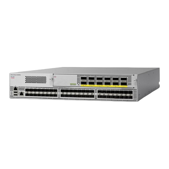
Product Overview
Introduces the Cisco Nexus 9396TX switch, its features, and user-replaceable components.
Preparing the Site (Chapter 2)
Temperature Requirements
Specifies the acceptable ambient operating and non-operating temperature ranges for the switch.
Humidity Requirements
Details the humidity levels the switch can withstand and recommendations for humid environments.
Altitude Requirements
States that altitude rating is based on power supply installed and refers to external reports.
Dust and Particulate Requirements
Discusses the impact of dust and particles on the switch and precautions to maintain a clean environment.
Minimizing EMI and RFI
Provides guidelines to reduce electromagnetic and radio frequency interference affecting other devices.
Shock and Vibration Requirements
Mentions the switch has been tested for shock, vibration, and earthquake standards.
Grounding Requirements
Explains the importance of earth-ground connection for the switch and how to achieve it.
Planning for Power Requirements
Details the switch's power supply configurations (redundancy) and power input considerations.
Airflow Requirements
Describes port-side intake/exhaust airflow, dual-direction airflow, and module coloring indicators.
Rack and Cabinet Requirements
Outlines the types of racks/cabinets and specific requirements for installation.
Clearance Requirements
Specifies the necessary clearances around the chassis for installation, cabling, and airflow.
Installing the Chassis (Chapter 3)
Installation Options
Explains rack-mount kit usage and compatible rack types (EIA, perforated cabinets).
Install a Rack
Steps for installing a standard 19-inch EIA data center rack or cabinet.
Unpacking and Inspecting
Procedures for unpacking the new chassis and inspecting it for damage or missing items.
Positioning the Chassis in the Rack
Guidance on planning the switch's location in the rack based on airflow direction.
Installing in a Two-Post Rack
Detailed steps for mounting the chassis in a two-post rack using center-mount brackets.
Installing in a Four-Post Rack
Instructions for installing the chassis in a four-post rack using bottom-support and front-mount brackets.
Grounding the Chassis
Procedures for grounding the chassis, either via the rack or a separate grounding cable.
Starting the Switch
Steps to connect power and power on the switch after installation.
Connecting the Switch to the Network (Chapter 4)
Setting Up Management Interface
How to connect to the switch's management port (MGMT ETH) for out-of-band management.
Uplink Connections
Information on connecting uplink modules (40/100-Gigabit optical ports) and speed configuration.
Downlink Connections
Details on connecting 10GBASE-T ports using RJ-45 connectors and supported cables.
Guidelines for Connecting Ports
Best practices for connecting fiber-optic and copper cables, including handling transceivers.
Maintaining Transceivers and Optical Cables
Guidelines for cleaning and handling transceivers and optical cables to ensure optimal performance.
Replacing Modules (Chapter 5)
Replacing Uplink Module
Step-by-step instructions for safely removing and installing uplink modules.
Replacing Fan Module
Procedures for replacing a fan module, including conditions for hot-swapping.
Replacing Power Supply Module
Steps for replacing AC, HVAC/HVDC, or DC power supply modules.
Rack Specifications (Appendix A)
Overview of Racks
Lists types of cabinets and racks suitable for switch installation.
General Cabinet/Rack Requirements
Specifies general requirements for EIA cabinets/racks, including mounting rail standards.
Requirements for Open Racks
Details specific requirements for mounting the chassis in open racks without side panels or doors.
Requirements for Perforated Cabinets
Outlines requirements for perforated cabinets, focusing on perforation patterns for airflow.
Cable Management Guidelines
Advice on planning for additional space for routing fiber optic and copper cables.
System Specifications (Appendix B)
Environmental Specifications
Lists operating and non-operating environmental parameters like temperature, humidity, and altitude.
Switch Dimensions
Provides the physical dimensions (width, depth, height) of the Cisco Nexus 9396TX switch.
Weights and Quantities
Lists weights and quantities for the switch chassis and various modules.
Transceiver and Cable Specifications
Directs users to resources for supported transceivers and cable specifications.
Switch Power Input Requirements
Details typical and maximum power consumption and heat dissipation for the switch.
Power Specifications
Provides detailed electrical specifications for 650-W AC, 1200-W HVAC/HVDC, and 930-W DC power supplies.
Power Cable Specifications
Lists part numbers and descriptions for AC, HVAC/HVDC, and DC power cables.
Regulatory Compliance Specifications
Summarizes regulatory compliance information, including safety and EMC standards.
LEDs (Appendix C)
Switch Chassis LEDs
Explains the status indicators (BCN, STS, ENV) on the switch chassis and their meanings.
Uplink Module LEDs
Describes the LEDs (STS, ACT, port) on the uplink module and their operational status indications.
Fan Module LEDs
Details the Status (STS) LED on the fan module and its operational status.
Power Supply LEDs
Explains the status indicators on the power supply modules (Okay, Fault) and their meanings.
Additional Kits (Appendix D)
Rack Mount Kit N9K-C9300-RMK
Lists and illustrates the contents of the 2-RU rack-mount kit.
Site Preparation and Maintenance Records (Appendix E)
Site Preparation Checklist
Provides a checklist of planning activities essential for a successful switch installation.
Contact and Site Information
A worksheet to record essential contact and site details for the installation.
Chassis and Module Information
Worksheets to record switch serial numbers, IP addresses, and module details.
Need help?
Do you have a question about the N9K-C9396TX and is the answer not in the manual?
Questions and answers