Cisco Nexus 93180YC-FX3 Installation Manual
Aci-mode switch
Hide thumbs
Also See for Nexus 93180YC-FX3:
- Hardware installation manual (56 pages) ,
- Hardware installation manual (70 pages)
Table of Contents
Advertisement
Advertisement
Chapters
Table of Contents

Subscribe to Our Youtube Channel
Related Manuals for Cisco Nexus 93180YC-FX3


Summary of Contents for Cisco Nexus 93180YC-FX3
- Page 1 Cisco Nexus 93180YC-FX3 ACI-Mode Switch Hardware Installation Guide First Published: 2021-02-01 Americas Headquarters Cisco Systems, Inc. 170 West Tasman Drive San Jose, CA 95134-1706 http://www.cisco.com Tel: 408 526-4000 800 553-NETS (6387) Fax: 408 527-0883...
- Page 2 Any products and features described herein as in development or available at a future date remain in varying stages of development and will be offered on a when-and if-available basis. Any such product or feature roadmaps are subject to change at the sole discretion of Cisco and Cisco will have no liability for delay in the delivery or failure to deliver any products or feature roadmap items that may be set forth in this document.
-
Page 3: Table Of Contents
Installation Options with Rack-Mount Kits Airflow Considerations Installation Guidelines Unpacking and Inspecting the Switch Installing the Switch Using the NXK-ACC-KIT-1RU Rack-Mount Kit Installing the Switch Using the N3K-C3064-ACC-KIT Rack-Mount Kit Grounding the Chassis Starting the Switch Cisco Nexus 93180YC-FX3 ACI-Mode Switch Hardware Installation Guide... - Page 4 System Specifications Environmental Specifications Switch Dimensions Switch and Module Weights and Quantities Transceiver and Cable Specifications Switch Power Input Requirements Power Specifications 650-W AC Power Supply Specifications 1200-W HVAC/HVDC Power Supply Specifications Cisco Nexus 93180YC-FX3 ACI-Mode Switch Hardware Installation Guide...
- Page 5 A P P E N D I X C LEDs Switch Chassis LEDs Fan Module LEDs Power Supply LEDs A P P E N D I X D Additional Kits Rack Mount Kit NXK-ACC-KIT-1RU Cisco Nexus 93180YC-FX3 ACI-Mode Switch Hardware Installation Guide...
- Page 6 Contents Cisco Nexus 93180YC-FX3 ACI-Mode Switch Hardware Installation Guide...
-
Page 7: Overview
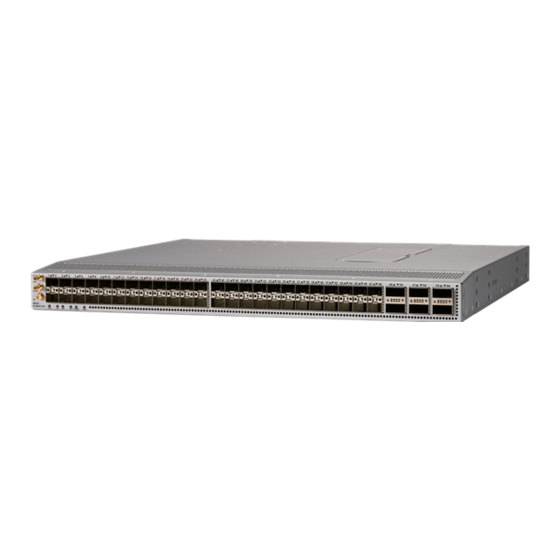
• Overview, on page 1 Overview The Cisco Nexus 93180YC-FX3 switch (N9K-C93180YC-FX3) is a 1-rack unit (RU), fixed-port switch designed for spine-leaf-APIC deployment in data centers. This switch has the following ports: • 48 100M/1/10/25-Gigabit Ethernet SFP28 ports (ports 1-48). - Page 8 The following figure shows the maximum configuration density of SFP-10G-T-X SFP+ transceivers for this switch. The following figure shows the switch features on the port side of the chassis. 1PPS and 10MHz SMB 48 100M/1/10/25-Gigabit ports Ethernet SFP28 ports Cisco Nexus 93180YC-FX3 ACI-Mode Switch Hardware Installation Guide...
- Page 9 1 (left) and 2 (right) Fan modules (4) with slots USB port numbered from 1 (left) to 4 (right) Console port ToD port The following figure shows the side of the chassis. Cisco Nexus 93180YC-FX3 ACI-Mode Switch Hardware Installation Guide...
- Page 10 If the switch has port-side exhaust airflow (blue coloring for fan modules), you must locate the ports in the hot aisle. If you locate the air intake in a hot aisle, the switch can overheat and shut down. Cisco Nexus 93180YC-FX3 ACI-Mode Switch Hardware Installation Guide...
-
Page 11: Preparing The Site
Altitude Requirements Altitude rating is based on power supply installed; see critical components list in the system CB report for altitude rating. Cisco Nexus 93180YC-FX3 ACI-Mode Switch Hardware Installation Guide... -
Page 12: Dust And Particulate Requirements
The wiring is unlikely to emit radio interference if you use a twisted-pair cable with a good distribution of grounding conductors. If you exceed the recommended distances, use a high-quality twisted-pair cable with one ground conductor for each data signal when applicable. Cisco Nexus 93180YC-FX3 ACI-Mode Switch Hardware Installation Guide... -
Page 13: Shock And Vibration Requirements
Planning for Power Requirements The switch includes two power supplies (1-to-1 redundancy with current sharing) in one of the following combinations: • Two 650-W AC power supplies (NEBS compliant) • Two 1200-W HVAC/HVDC power supplies Cisco Nexus 93180YC-FX3 ACI-Mode Switch Hardware Installation Guide... - Page 14 IEC 60950 based safety standards. Note We recommend 8-AWG wire for DC installations in the U.S. Note For the power cables to use with the power supplies, see Power Cable Specifications, on page Cisco Nexus 93180YC-FX3 ACI-Mode Switch Hardware Installation Guide...
-
Page 15: Airflow Requirements
(for proper mounting of the bottom-support brackets or other mounting hardware). Also, you must have power receptacles that are located within reach of the power cords that are used with the switch. Cisco Nexus 93180YC-FX3 ACI-Mode Switch Hardware Installation Guide... -
Page 16: Clearance Requirements
17.3 in (43.9 cm) Width of the front clearance area (equal to the width of the chassis with two rack-mount brackets that are attached to it). 19.0 in (43.3 cm) Cisco Nexus 93180YC-FX3 ACI-Mode Switch Hardware Installation Guide... - Page 17 Preparing the Site Clearance Requirements Note Both the front and rear of the chassis must be open to both aisles for airflow. Cisco Nexus 93180YC-FX3 ACI-Mode Switch Hardware Installation Guide...
- Page 18 Preparing the Site Clearance Requirements Cisco Nexus 93180YC-FX3 ACI-Mode Switch Hardware Installation Guide...
-
Page 19: Installing The Switch Chassis
Starting the Switch, on page 26 Safety Before you install, operate, or service the switch, see the Regulatory, Compliance, and Safety Information for the Cisco Nexus 3000 and 9000 Series for important Safety Information. Warning Statement 1071 Warning Definition IMPORTANT SAFETY INSTRUCTIONS Before you work on any equipment, be aware of the hazards involved with electrical circuitry and be familiar with standard practices for preventing accidents. -
Page 20: Installation Options With Rack-Mount Kits
You can install the switch using the following rack-mount options: • Rack-mount kit (NXK-ACC-KIT-1RU) which you can order from Cisco. This option offers you easy installation, greater stability, increased weight capacity, added accessibility, and improved removability with front and rear removal. -
Page 21: Unpacking And Inspecting The Switch
Unpacking and Inspecting the Switch Before you install the switch, be sure to unpack and inspect the switch for damage or missing components. If anything is missing or damaged, contact your customer service representative immediately. Cisco Nexus 93180YC-FX3 ACI-Mode Switch Hardware Installation Guide... -
Page 22: Installing The Switch Using The Nxk-Acc-Kit-1Ru Rack-Mount Kit
• You have inspected the switch shipment to ensure that you have everything ordered. • Make sure that the switch rack-mount kit includes the following parts: • Front rack-mount brackets (2) • Rear rack-mount brackets (2) • Slider rails (2) Cisco Nexus 93180YC-FX3 ACI-Mode Switch Hardware Installation Guide... - Page 23 Note Depending on the chassis depth, the back rack-mount bracket may not fit. In that case the back rack-mount bracket is not needed. Cisco Nexus 93180YC-FX3 ACI-Mode Switch Hardware Installation Guide...
- Page 24 Holding the switch with both hands, position the two rear rack-mount brackets on the switch between the rack or cabinet posts that do not have slider rails attached to them (see the following figure). Cisco Nexus 93180YC-FX3 ACI-Mode Switch Hardware Installation Guide...
- Page 25 Tighten the 10-32 screws to 20 in-lb (2.26 N·m) or tighten the 12-24 screws to 30 in-lb (3.39 N·m). Step 5 If you attached a grounding wire to the chassis grounding pad, connect the other end of the wire to the facility ground. Cisco Nexus 93180YC-FX3 ACI-Mode Switch Hardware Installation Guide...
-
Page 26: Installingtheswitchusingthen3K-C3064-Acc-Kitrack-Mount Kit
(3 inches [7.6 mm] minimum) and module handles (1 inch [2.5 mm] minimum). Cisco Nexus 93180YC-FX3 ACI-Mode Switch Hardware Installation Guide... - Page 27 Attach the guide to the chassis using two M4 screws (see Callout 4 or 8 in the previous figure). Tighten the screws to 12 in-lb (1.36 N·m) of torque. c) Repeat Step 2 for the other rear rack-mount bracket on the other side of the switch. Cisco Nexus 93180YC-FX3 ACI-Mode Switch Hardware Installation Guide...
- Page 28 Holding the switch with both hands, position the two rear rack-mount brackets on the switch between the rack or cabinet posts that do not have slider rails attached to them (see the following figure). Cisco Nexus 93180YC-FX3 ACI-Mode Switch Hardware Installation Guide...
- Page 29 Holding the chassis level, insert two screws (12-24 or 10-32, depending on the rack type) in each of the two front rack-mount brackets (using a total of four screws) and into the cage nuts or threaded holes in the vertical rack-mounting rails (see the following figure). Cisco Nexus 93180YC-FX3 ACI-Mode Switch Hardware Installation Guide...
-
Page 30: Grounding The Chassis
You can also ground the chassis, which is required if the rack is not grounded, by attaching a customer-supplied grounding cable. Attach the cable to the chassis grounding pad and the facility ground. Cisco Nexus 93180YC-FX3 ACI-Mode Switch Hardware Installation Guide... - Page 31 Step 3 Secure the grounding lug to the chassis grounding pad with two M4 screws, see the previous figure. Tighten the screws to 11 to 15 in-lb (1.24 to 1.69 N·m) of torque. Cisco Nexus 93180YC-FX3 ACI-Mode Switch Hardware Installation Guide...
-
Page 32: Starting The Switch
• When connecting to an HVAC power source, insert the C14 or LS-25 plug in a receptacle for the HVAC power source. • When connecting to an HVDC power source, do the following: Cisco Nexus 93180YC-FX3 ACI-Mode Switch Hardware Installation Guide... - Page 33 A setup utility automatically launches the first time that you access the switch and guides you through the basic configuration. For instructions on how to configure the switch and check module connectivity, see the appropriate Cisco Nexus 9000 Series configuration guide.
- Page 34 Installing the Switch Chassis Starting the Switch Cisco Nexus 93180YC-FX3 ACI-Mode Switch Hardware Installation Guide...
-
Page 35: Aci Fabric Topology
As shown in the following figure, each APIC is connected to one or two leaf switches and each leaf switch should be connected to every spine switch in the same fabric. Cisco Nexus 93180YC-FX3 ACI-Mode Switch Hardware Installation Guide... -
Page 36: Preparing To Connect To Other Devices
Cisco equipment. In situations where long parallel cable runs cannot be separated by at least 3.3 feet (1 meter), we recommend that you shield any potential noise sources by housing them in a grounded metallic conduit. -
Page 37: Connecting Leaf Switches To Apics
Connecting Leaf Switches to APICs You must downlink one or two (recommended for redundancy) Cisco Nexus 9300 platform ACI-mode leaf switches to each Application Policy Infrastructure Controller (APIC) in your ACI fabric. The type of virtual interface card (VIC) installed on the APIC determines the types of interface cables that you can use to connect the leaf switches to the APICs. - Page 38 Connect the other end of the interface cable to a downlink port on a leaf switch. • For a Cisco 10GBASE-LR or -SR transceiver and cable, insert the transceiver into a downlink optical port on a leaf switch before connecting the cable to the transceiver.
-
Page 39: Connecting Leaf Switches To Spine Switches
You cannot include NX-OS line cards in the same chassis when running in ACI mode. Note Multiple uplinks from a leaf switch to a spine switch is supported. A symmetrical topology is recommended so that all devices have equal access to resources. Cisco Nexus 93180YC-FX3 ACI-Mode Switch Hardware Installation Guide... -
Page 40: Installing A Gigabit Ethernet Module (Gem)
You have two first-generation Cisco Nexus 9000 Series switches comprising a virtual port channel (vPC). You are migrating to two second-generation Cisco Nexus 9000 Series switches using the same cables. First-generation Cisco Nexus 9000 Series switches include those switches that do not contain an EX or an FX in the PID (product identification). -
Page 41: Setting Up An Optional Console Interface
Connecting the Switch to the ACI Fabric Setting Up an Optional Console Interface Second-generation Cisco Nexus 9000 Series switches include those switches that have an EX or an FX in the PID. Move any APIC controllers that are connected to the migrating vPC first-generation switches to any other switches in the fabric and wait for the APIC cluster to become "Fully Fit". -
Page 42: Setting Up An Optional Management Connection
DB-9 connector on the other end of the cable to the serial port on the console device. What to do next You can now perform the initial configuration for the switch (see the Cisco ACI Getting Started Guide). Setting Up an Optional Management Connection You can optionally set up an out-of-band management connection for monitoring and troubleshooting purposes. -
Page 43: Maintaining Transceivers And Optical Cables
Transceivers and fiber-optic cables must be kept clean and dust free to maintain high signal accuracy and prevent damage to the connectors. Contamination increases attenuation (loss of light) and should be below 0.35 dB. Cisco Nexus 93180YC-FX3 ACI-Mode Switch Hardware Installation Guide... - Page 44 • Inspect routinely for dust and damage. If you suspect damage, clean and then inspect fiber ends under a microscope to determine if damage has occurred. Cisco Nexus 93180YC-FX3 ACI-Mode Switch Hardware Installation Guide...
- Page 45 • There must be an earth ground connection to the chassis that you are installing the replacement module. AC power supplies connected to AC power sources are automatically grounded through their power cable. Cisco Nexus 93180YC-FX3 ACI-Mode Switch Hardware Installation Guide...
- Page 46 Depending on the outlet receptacle on your power distribution unit, you might need the optional jumper Note cable to connect the switch to your outlet receptacle. e) Verify that the power supply is operational by making sure that the power supply LED is green. Cisco Nexus 93180YC-FX3 ACI-Mode Switch Hardware Installation Guide...
- Page 47 • Standard 19-inch (48.3 cm) (two- or four-post EIA cabinet or rack, with mounting rails that conform to English universal hole spacing per section 1 of ANSI/EIA-310-D-1992). For more information, see Requirements Specific to Perforated Cabinets, on page Cisco Nexus 93180YC-FX3 ACI-Mode Switch Hardware Installation Guide...
- Page 48 • The roof should be perforated with at least a 20 percent open area. • The cabinet floor should be open or perforated to enhance cooling. The Cisco R Series rack conforms to these requirements. Cable Management Guidelines To help with cable management, you might want to allow additional space in the rack above and below the chassis to make it easier to route all of the fiber optic or copper cables through the rack.
-
Page 49: Environmental Specifications
6000 to 13000 feet (1828.8 to 3962.4 meters) (-5°C to 45°C; system operating temperature, 100% Load Short Term Condition) 6000 to 13000 feet (1828.8 to 3962.4 meters) (-5°C to 55°C; system operating temperature, 60% Load Long Term Condition) Cisco Nexus 93180YC-FX3 ACI-Mode Switch Hardware Installation Guide... -
Page 50: Switch Dimensions
Some power supplies have capabilities that are greater than the maximum power requirements for a switch. To determine the power consumption characteristics for the switch, use the typical and maximum requirements that are listed in the following table. Cisco Nexus 93180YC-FX3 ACI-Mode Switch Hardware Installation Guide... -
Page 51: Power Specifications
Power supply standby voltage 12 VDC Efficiency rating Climate Savers Platinum Efficiency (80Plus Platinum certified) Form factor RSP1 1200-W HVAC/HVDC Power Supply Specifications These specifications apply to the 1200-W HVAC/HVDC (N9K-PUV-1200W) power supplies. Cisco Nexus 93180YC-FX3 ACI-Mode Switch Hardware Installation Guide... - Page 52 23 A at -48 VDC Maximum output power per power supply 930 W Maximum inrush current 35 A (sub-cycle duration) Maximum hold-up time 8 ms at 930 W Power supply output voltage 12 VDC Cisco Nexus 93180YC-FX3 ACI-Mode Switch Hardware Installation Guide...
-
Page 53: Power Cable Specifications
250 VAC, 10 A, CEI 23-16/VII plug, 8.2 feet (2.5 m) Japan CAB-C13-C14-2M-JP Power Cord Jumper, C13-C14 Connectors, 6.6 feet (2.0 m) North America CAB-9K12A-NA 125 VAC, 13 A, NEMA 5-15 plug, 8.2 feet (2.5 m) Cisco Nexus 93180YC-FX3 ACI-Mode Switch Hardware Installation Guide... - Page 54 HVAC 2-foot (0.6 m) cable with Saf-D-Grid and RT connector 277V AC CAB-HVDC-3T-2M HVDC 6.6-foot (2.0 m) cable with Saf-D-Grid and three terminal connectors 300V AC / 400V DC (+200/-200 V DC) Cisco Nexus 93180YC-FX3 ACI-Mode Switch Hardware Installation Guide...
-
Page 55: Regulatory Standards Compliance Specifications
Products should comply with CE Markings according to directives 2004/108/EC and 2006/95/EC. Safety • CAN/CSA-C22.2 No. 60950-1 Second Edition • EN 60950-1 Second Edition • IEC 60950-1 Second Edition • IEC 623681 • AS/NZS 60950-1 • GB4943 Cisco Nexus 93180YC-FX3 ACI-Mode Switch Hardware Installation Guide... - Page 56 • CNS13438 Class A EMC: Immunity • EN55024 • CISPR24 • EN300386 • KN 61000-4 series RoHS The product is RoH-6 compliant with exceptions for leaded-ball grid-array (BGA) balls and lead press-fit connectors. Cisco Nexus 93180YC-FX3 ACI-Mode Switch Hardware Installation Guide...
-
Page 57: Appendix
Temperature exceeds the major alarm threshold. The switch is not receiving power. Green Fans and power supply modules are operational. Amber At least one fan or power supply module is not operating. Cisco Nexus 93180YC-FX3 ACI-Mode Switch Hardware Installation Guide... - Page 58 ToD, 1PPS, 10MHz are not valid. Fan Module LEDs The fan module LED is located below the air holes on the front of the module. Cisco Nexus 93180YC-FX3 ACI-Mode Switch Hardware Installation Guide...
- Page 59 Power supply is not receiving power. Green Flashing amber Power supply warning—possibly one of the following conditions: • High voltage • High power • Low voltage • Slow power supply fan Cisco Nexus 93180YC-FX3 ACI-Mode Switch Hardware Installation Guide...
- Page 60 LEDs Power Supply LEDs Cisco Nexus 93180YC-FX3 ACI-Mode Switch Hardware Installation Guide...
- Page 61 Not applicable Hazardous substances list for customers in China The following table lists and illustrates the console cable (CAB-CONSOLE-RJ45) that can be ordered. Illustration Description Quantity Console cable with DB-9F and RJ-45F connectors Cisco Nexus 93180YC-FX3 ACI-Mode Switch Hardware Installation Guide...
- Page 62 Additional Kits Additional Kits Cisco Nexus 93180YC-FX3 ACI-Mode Switch Hardware Installation Guide...
Need help?
Do you have a question about the Nexus 93180YC-FX3 and is the answer not in the manual?
Questions and answers