Table of Contents
Advertisement
Quick Links
- 1 Table of Contents
- 2 General Information ���������������������������������������� 4-7 Checking Airflow
- 3 Electrical and Physical Data
- 4 Specifications
- 5 Operational Issues
- 6 Location ����������������������������������������������������������������������12 Diagnostics
- 7 Tubing Connections ���������������������������������������������������25 General Troubleshooting Chart
- Download this manual
WARNING:
RECOGNIZE THIS SYMBOL
AS AN INDICATION OF
IMPORTANT SAFETY
INFORMATION
WARNING
THESE INSTRUCTIONS
ARE INTENDED AS AN AID
TO QUALIFIED, LICENSED
SERVICE PERSONNEL FOR
PROPER INSTALLATION,
ADJUSTMENT, AND
OPERATION OF THIS UNIT.
READ THESE INSTRUCTIONS
THOROUGHLY BEFORE
ATTEMPTING INSTALLATION
OR OPERATION. FAILURE
TO FOLLOW THESE
INSTRUCTIONS MAY RESULT
IN IMPROPER INSTALLATION,
ADJUSTMENT, SERVICE,
OR MAINTENANCE
POSSIBLY RESULTING IN
FIRE, ELECTRICAL SHOCK,
PROPERTY DAMAGE,
PERSONAL INJURY, OR
DEATH.
Do not destroy this manual.
Please read carefully and
keep in a safe place for future
reference by a serviceman.
[ ] indicates metric conversions.
92-105074-04-00 (1/15) Printed in USA
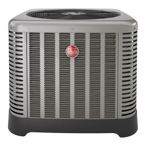
R-410A HEAT PUMP
OUTDOOR UNITS
INSTALLATION INSTRUCTIONS
RP13 (13 SEER)
RP14 (14 SEER) AND RP15 (15 SEER)
ST-A1226-01-00
Advertisement
Table of Contents

Summarization of Contents
Important Safety Information
Safety Warnings and Precautions
Covers critical safety precautions, potential hazards, and warnings for installation and operation.
General Information
Product Receiving and Application
Details product inspection upon delivery and the process for specifying heat pump equipment.
Proper Installation Practices
Matching System Components
Emphasizes the necessity of matching all system components for proper installation and performance.
Installation Location Guidance
Choosing an Outdoor Unit Location
Discusses operational issues and environmental factors for selecting the unit's placement.
Space Limitations and Customer Satisfaction
Provides clearance guidelines for confined spaces and placement for noise reduction.
Unit Mounting and Elevation
Covers safety for mounting elevated units and general elevation guidelines.
High Wind and Seismic Load Tie-Down
Recommends manufacturer-approved tie-down methods for securing equipment against wind and seismic loads.
Tools and Refrigerant Handling
R-410A Installation Tools and Specifications
Lists required tools, refrigerant specifications, and safety notes for R-410A systems.
R-410A Quick-Reference Guide
Provides essential information and guidelines for working with R-410A refrigerant.
Tubing and Line Set Installation
Replacement Unit and Indoor Coil Considerations
Addresses replacing units and using approved indoor coils for R-410A systems.
Interconnecting Tubing and Refrigerant Charge
Covers tubing practices, refrigerant level adjustments, and line set calculations.
Liquid Line and Suction Line Selection
Explains liquid line selection and importance of suction line sizing for system performance.
Long Line Set Application Guidelines
Details considerations for long line sets, including oil level adjustments and application limits.
Refrigerant Migration and Tubing Installation
Discusses refrigerant migration during off-cycle and general tubing installation practices.
Tubing Connections and Leak Testing
Covers procedures for making tubing connections and performing leak tests on the system.
Wiring Installation
Control Wiring Procedures
Details low-voltage control wiring, thermostat requirements, and wire sizing.
Power Wiring and Grounding
Explains power wiring requirements, voltage ranges, and the critical importance of grounding.
Start-Up Procedures
Initial Unit Start-Up and Airflow Check
Covers initial start-up steps, including crankcase heater energization and airflow verification.
System Evacuation and Leak Testing
Details the critical procedures for system evacuation and performing final leak testing.
Refrigerant Charge Verification
Explains how to check refrigerant charge using weight, pressures, and subcooling methods.
Finishing Installation Steps
Covers final installation tasks after charging, including disconnecting gauges and thermostat setup.
Components and Controls
Compressor Crankcase Heat (CCH)
Explains the function of crankcase heaters for scroll compressors and their recommended use.
Hard-Start Components
Mentions availability of hard-start components for special cases to reduce light dimming.
High- and Low-Pressure Controls (HPC/LPC)
Describes the function of High- and Low-Pressure Controls (HPC/LPC) in protecting the compressor.
Demand Defrost Control Operation
Details the demand defrost control's logic, testing, and high/low pressure monitoring.
Accessories
Heat Pump Thermostat Warning Light Kit
Describes a kit that senses compressor lockouts and alerts the thermostat's service light.
Time Delay Control (TDC)
Explains the function of the Time Delay Control (TDC) to prevent compressor damage.
Remote Outdoor Temperature Model
Details a kit providing a longer remote sensor for improved thermostat temperature display.
Low Ambient Control (LAC)
Explains the Low Ambient Control (LAC) function in managing head pressure at lower temperatures.
Diagnostics and Troubleshooting
Cooling Mechanical Checks Flowchart
Provides a flowchart to diagnose mechanical issues in cooling mode based on system pressures.
Heating Mechanical Checks Flowchart
Offers a flowchart for diagnosing mechanical problems in heating mode, considering pressure and airflow.
Defrost Mechanical Checks Flowchart
Presents a flowchart for troubleshooting defrost system issues, including no, incomplete, or excessive defrost.
General Troubleshooting Chart
Lists common system symptoms, their possible causes, and recommended remedies for troubleshooting.
Service Analyzer Charts for Compressor Issues
Details causes and remedies for compressor overheating, electrical faults, and flooded starts.
Service Analyzer Charts for Contamination and Lubrication
Addresses contamination issues and problems related to loss of lubrication, including slugging.
Service Analyzer Charts for Expansion Valves
Covers troubleshooting for Thermostatic Expansion Valves (TEVs) and flooding issues.
Troubleshooting Tips for Cooling and Heating Modes
Correlates system problems with indicator readings like pressure and superheat for cooling and heating.
Wiring Diagrams
Single Phase Heat Pump Wiring Diagram
Presents the electrical wiring diagram for a single-phase heat pump with demand defrost control.
Three Phase Heat Pump Wiring Diagrams
Shows wiring diagrams for 208/230V and 460/575V three-phase heat pumps with defrost control.


Need help?
Do you have a question about the RP15 and is the answer not in the manual?
Questions and answers