Table of Contents
Advertisement
Quick Links
Advertisement
Table of Contents
Troubleshooting

Related Manuals for ROYAL CLIMA RC-RNX28HN


Summary of Contents for ROYAL CLIMA RC-RNX28HN
- Page 1 ROYAL CLIMA 2022 R410A Renaissance On/Off...
-
Page 2: Table Of Contents
CONTENTS Part I : Technical Information ................... 3 1. Summary ........................3 1-1 Appearance ..........................3 1-2 Model List..........................4 2. Outline Dimension Diagram ..................5 3. Function and Control ....................7 3-1 T-Style ............................7 4. Refrigerant System Diagram ..................14 4-1 Cooling Only ........................... 14 4-2 Cooling &... -
Page 3: Part I : Technical Information
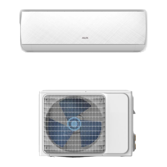
Part I : Technical Information 1. Summary 1-1 Appearance Indoor Unit ➢ Outdoor Unit ➢ Note: The outdoor grille can be replaced. -
Page 4: Model List
1-2 Model List MODEL RC-RNX24HN RC-RNX28HN RC-RNX35HN RC-RNX55HN... -
Page 5: Outline Dimension Diagram
2. Outline Dimension Diagram The following data is for reference only and the actual size may vary.) 2-1 Indoor Unit(Unit: mm) RC-RNX24HN, RC-RNX28HN, RC-RNX35HN RC-RNX55HN... - Page 6 2-2 Outdoor Unit(Unit: mm) RC-RNX24HN, RC-RNX28HN RC-RNX35HN RC-RNX55HN...
-
Page 7: Function And Control
3. Function and Control 3-1 T-Style 1) Remote Controller Introductions ● Carefully read this “instructions” for safe and correct use of the air-conditioner. ● carefully keep the “instructions” manual as it can be referred to at any time. ➢ Buttons description... - Page 8 1. ON/OFF Button * Press this button to turn on/off the unit. * This will clear the existing timer and SLEEP settings. 2. MODE Button * Press this button, you can select the running mode as follows: Note: HEAT mode is not available for cool only units. 3.
- Page 9 Note: The temperature cannot be set in AUTO or Fan mode. 8. MENU & OK Button * Press MENU button to enter the function selection mode. Then press to choose the function which you want. After, press OK button, turn on this function.
- Page 10 large area, be cautious to use the ECO mode. 13. SLEEP * When the unit is on, press MENU button ,then press , to choose the “SLEEP” character, when the “SLEEP” character will blink, and press the “OK” button to highlight (not highlight ) the “SLEEP” character , which will activate (deactivate) the function of sleep mode.
- Page 11 * When the unit is off, press the “MENU” button, then press , choose the “Anti-F” character , when the “Anti-F” character will blink, and press the “OK” button to highlight (not highlight) the “Anti-F” character , which will activate (deactivate) the Anti-F function.
- Page 12 (cooling), it will continue to operate for about 3 minutes to dry the moisture on the evaporator, so as to prevent the accumulation of bacteria on the evaporator, which causes fungus and strange smell and is harmful to the health. * When the unit is off, press the “MENU”...
- Page 13 5. Press the “ON/OFF” button again, the air-conditioner stops. Note: The cold wind type has no heating function. ★ Fan operation mode 1. Press the “MODE” button, select the fan operation mode. 2. By pressing the “SPEED” button, you can select the motor speed from LOW, MID, HIGH.
-
Page 14: Refrigerant System Diagram
4. Refrigerant System Diagram 4-1 Cooling Only ➢ Cooling Mode Indoor Unit Outdoor Unit ➢ Cooling Cycle Steam-gas of low pressure Indoor heat exchanger Compressor (Evaporation) (Compression) Liquid of low Gas of high pressure & pressure temperature (also a little gas) Super cooled liquid of high pressure Capillary... -
Page 15: Cooling & Heating
4-2 Cooling & Heating ➢ Cooling Mode Indoor Unit Outdoor Unit ➢ Cooling Cycle Steam-gas of low pressure Indoor heat exchanger Compressor (Evaporation) (Compression) 4-way valve (Heat pump only) Liquid of low pressure Gas of high pressure (also a little gas) &... - Page 16 ➢ Heating Mode Indoor Unit Outdoor Unit ➢ Heating Cycle Gas of high pressure & temperature Indoor heat exchanger Compressor (Evaporation) (Compression) 4-way valve (Heat pump only) Super cooled liquid of low pressure Steam-gas of low pressure Super cooled liquid of high pressure Capillary Outdoor heat exchanger...
-
Page 17: Electrical Part
5. Electrical Part The diagrams listed below for reference only, please refer to the actual product. 5-1 Electrical Wiring Diagram ➢ Indoor Unit 09K、12K、18K... - Page 18 ➢ outdoor Unit RC-RNX24HN、RC-RNX28HN、RC-RNX35HN, RC-RNX55HN...
-
Page 19: Part Ii : Installation And Maintenance
Part II : Installation and Maintenance 6. Main Tools for Installation and Maintenance... -
Page 20: Installation
7. Installation 7-1 Notes for Installation Important Notices ⚫ Before installation, please contact with local authorized maintenance center, if unit is not installed by the authorized maintenance center, the malfunction may not solved, due to discommodious contact. ⚫ The air conditioner must be installed by professionals according to the national wiring rules and this manual. -
Page 21: Installation Of Indoor Unit
⚫ The power cable enables communication between the indoor and outdoor units. You must first choose the right cable size before preparing it for connection. Grounding Requirements ⚫ The air conditioner is the type I electrical appliance and must ensure a reliable grounding. - Page 22 1. The wall for installation of the indoor unit shall be hard and firm, so as to prevent vibration. 2. Use the "+" type screw to fasten the peg board, horizontally mount the peg board on the wall, and ensure the lateral horizontal and longitudinal vertical. 3.
- Page 23 Tightening torque table Torque(N·m) The size of pipe(mm) Φ6/Φ6.35 15~25 Φ9 /Φ9.5 2 35~40 Φ12/Φ12.7 45~60 Φ15.88 73~78 Φ19.05 75~80 ➢ Wrap the Piping 1. Use the insulation sleeve to wrap the joint part the indoor unit and the connection pipe, and then use insulating material to pack and seal insulation pipe, to prevent generation of condensate water on the joint part.
-
Page 24: Installation Of Outdoor Unit
● Fix the cable reliably with fasteners (Pressing board). ● Put the E-parts cover back in its original place and fasten it with screws. Wiring Diagram NOTE: ※ This manual usually includes the wiring mode for the different kind of A/C. We cannot exclude the possibility that some special type of wiring diagrams are not included. - Page 25 ➢ Install the connection pipe Connect the Outdoor Unit with Connecting Pipe: Aim the counter-bore of the connecting pipe at the stop valve, and tighten the Taper nut with fingers. Then tighten the Taper nut with a torque wrench. ★When prolonging the piping, extra amount of refrigerant must be added so that the operation and performance of the air conditioner will not be compromised.
- Page 26 Wiring Diagram NOTE: ※ This manual is usually includes the wiring mode for the different kind of A/C. We cannot exclude the possibility that some special type of wiring diagrams are not included. ※ The diagram are for reference only. If the entity is difference with this wiring diagram, please refer to the detailed wiring diagram adhered on the unit which you purchased.
-
Page 27: Check After Installation And Test Operation
vacuum pumping method) Before working on the air conditioner, remove the cover of the stop valve(gas and liquid valves)and be sure to retighten it afterward.(to prevent the potential air leakage) 1. To prevent air leakage and spilling tighten all connecting nut of all flare tubes. 2. - Page 28 ④ Check that no foreign matter or tools are left inside the unit. ★ Leak test of the refrigerant Depending on the installation method, the following methods may be used to check for suspect leak, on areas such as the four connections of the outdoor unit and the cores of the cut-off valves and t-valves: ①...
-
Page 29: Maintenance
8. Maintenance 8-1 Troubleshooting Guide Many error codes many appears on this air conditionor, and this troubleshooting guide is prepared for the maintenance personnel to detect the error position and the parts to be replaced during the troubleshooting process. In this Guide, the Troubleshooting Method is guided by the Error Name, and the Reference Code under the General Index is the error code of the Indoor Unit unit of the mainstream model supplied by the Company. - Page 30 Example: Cause: explain the principle of the specific error. Explanation Inspection path: The basic order of troubleshooting. Related key of error position Tools required Tools that should be carried for such troubleshooting, and for inspection replacing parts that may be necessary for such error. Frequent Any possibly broken part related to the error may be the parts that problematic...
- Page 31 (1)E0 - Overcurrent Protection of Indoor Unit Cause: The main PCB detects that the working current of the system exceeds the upper limit of protection, and will indicate "indoor unit Explanation of overcurrent protectin:. The air conditioner stopps running for error protection and displays the failure code E0.
- Page 32 (2)E1- Indoor Unit temperature sensor error Cause: The detection of short circuit or open circuit of Indoor Unit temperature sensor during the inspection of main PCB in the Indoor Explanation of Unit machine, indicated by “Indoor Unit temperature sensor error”. error Inspection path: Sensor→Sensor wire→Connectors→Indoor Unit main PCB...
- Page 33 (3)E2 -Outdoor Unit coil sensor error Cause: The detection of short circuit or open circuit of Outdoor Unit coil sensor during the inspection of Outdoor Unit main PCB, indicated Explanation of by “Outdoor Unit coil sensor error”. error Inspection path: Sensor→Sensor wire→Connectors→Outdoor Unit main PCB Tools required Multimeter, 20KΩ...
- Page 34 (4)E3 -Indoor Unit coil sensor error Cause: The detection of short circuit or open circuit of Indoor Unit coil sensor during the inspection of Indoor Unit main PCB, indicated Explanation of by “Indoor Unit coil sensor error”. error Inspection path: Sensor→Sensor wire→Connectors→Indoor Unit main PCB Tools required Multimeter,, 5KΩ...
- Page 35 (5)E4 -Indoor Unit motor error of wall mounted air conditioner(PG motor) Cause: PG motor is equipped with speed feedback signal line. When the feedback signal of speed is not received by the Indoor Unit main PCB, it has no way to recognize the rotating speed of motor, which will be indicated as “Indoor Unit motor error”.
- Page 36 (6) E4- Indoor Unit motor error of wall mounted air conditioner (DC motor) Cause: The Indoor Unit motor of some highly energy efficient models is DC motor using a green plug through which the Indoor Unit main PCB can drive the motor and sense the current rotational speed feedback.
- Page 37 (7) Eb- Indoor EE Failure Cause: Many parameters need to be preset for the running of the indoor unit of the air conditioner and such parameters are placed in a data storage 8-feet chip, which is called "EEPROM" or "EE" for short. The motor on the Indoor Unit main PCB can only work after reading the data stored in EE and if not read, the failure code "Outdoor EE Failure"...
- Page 38 (8) P2- High-pressure protection Cause: In standby state or when the equipment is running, the High-pressure switch is disconnected three times (within 20 minutes) Explanation of and reported as " High-pressure protection"; error Inspection path: High-pressure switch cable → connector → High-pressure switch →...
- Page 39 (9) P3- Liquid Deficiency Protection Cause: The liquid volume of the system is less than 30%, which leads to non-refrigeration and liquid shortage protection. Explanation of Inspection path: whether the valves of the outdoor unit are opened → error whether the evaporator, condenser, connectoin pipe are damanged or cracked →...
-
Page 40: Troubleshooting For Normal Malfunction
8-2 Troubleshooting for Normal Malfunction ➢ The Foremost Inspecting Items ① The input voltage must be within +10% tolerance of the rated Voltage. If it is not the case, the air-conditioner will probably not work normally. ② Check the connecting cord between indoor unit and outdoor unit to see if it is properly connected. - Page 41 ①No Power Display (1) Items a) Check if the input voltage is correct? b) Check if the AC power supply connecting is correct? c) Check if the output voltage of the manostat L7805 (IC2) is correct? (2) Trouble shooting procedure...
- Page 42 ②The Indoor Motor Does Not Work (1) Items a) Check if the indoor Motor is connected correctly to the connector (CN8)? b) Check if the AC input voltage is correct? c) Check if the IC of indoor Motor is connected correctly to the connector (CN2)? d) Check if the capacity of indoor Motor is connected correctly to the connector (CN8)? (2) Trouble shooting procedure...
- Page 43 ③The Outdoor Unit Does Not Work (1) Items a) Check if the input voltage is correct? b) Check if the wire connection of the outdoor connecting terminal is correct? (2) Trouble shooting procedure...
- Page 44 ④The Step Motor Does Not Work (1) Items a) Check if the input voltage is correct? b) Check if the step motor controlling the up-down movement firmly connected to Cn2? (2) Trouble shooting procedure...
- Page 45 ⑤Heating Mode Can Work, But No Hot Air Blow (1) Check if the set temperature is lower than the indoor temperature? (2) Check if the indoor PCB is connected to the terminal correctly?
- Page 46 ⑥ Remote Control Can Not Work Trouble shooting procedure...
-
Page 47: Exploded Views And Parts List
9. Exploded Views and Parts List 9-1 Indoor Unit ➢ Exploded View... - Page 48 ➢ Part List Part Name Quantity Part Name Quantity Evaporator assembly panel Evaporator left side Display board 13.1 carriage Evaporator part A Air louver 13.2 Evaporator part B Filter 13.3 Medium frame Motor cover decorative strip Left side panel IDU Motor Medium frame Mounting plate assembly Right side panel...
-
Page 49: Outdoor Unit
9-2 Outdoor Unit ➢ Exploded View... - Page 50 ➢ Part List Part Name Quantity Part Name Quantity Right side board Condenser assembly E-parts cover Condenser assembly 17.1 Valve plate Capillary assembly 17.2 Stop valve Top cover Stop valve 4-way valve tubing assembly Compressor assembly 4-way valve 19.1 Chassis assembly Suction pipe assembly 19.2 Chassis...
-
Page 51: Removal Procedure
10. Removal Procedure Stop operation of the air conditioner and remove the power cord before repairing the unit. 10-1 Indoor Unit Parts Procedure Diagram 1) Turn off the power, hold the middle panel with the middle finger, Front Panel 2) open the panel upwards, remove the panel fixing shaft, remove... - Page 52 Loosen the clasps of the medium medium frame , remove the frame medium frame. 1) Take all the connector of PCB upper side out.(Including Power cord) Electrical 2) Detach the outdoor unit Parts connection wire from (Main PCB) terminal block. 3) If pulling the main PCB up, it will be taken out.
- Page 53 1) Loosen fixing screws and detach the motor holder. 2) Loosen fixing screw of Motor motor. (with a M6 wrench) & 3) Detach the motor from the Cross Motor motor. 4) Detach the motor from the left holder bearing. Remove screws on volute and volute remove the volute.
-
Page 54: Outdoor Unit
10-2 Outdoor Unit Part Procedure Diagram Turn off the power , remove connection screws among top cover plate, front panel top cover and right side panel, then remove the top cover. Remove connection screws between the panel grille front grille and the front panel .Then remove the front grille. - Page 55 Remove connection screws connecting Right side the right side panel with the valve support panel and electric box, then remove the right side panel. Remove the nut fixing the blade and then Axial flow remove the axial flow blade. blade Remove the tapping screws fixing the Outer motor motor, pull out the lead-out wire and...
- Page 56 Loosen the wire and disconnect the Electric box terminal. Lift to remove the electric box assy assy. Loosen the screws of the partition board, Partition then lift and pull the partition board to board remove . Remove connection screws connecting left side the left side support plate with the valve support plate...
- Page 57 Remove the screws fixing the gas valve. Unsolder the welding spot connecting gas valve and air return Stop valve pipe and remove the gas valve. assembly Remove the screws fixing liquid valve. Unsolder the welding spot connecting liquid valve and remove the liquid valve.
- Page 58 Loosen fixing screws Connecting chassis, condenser and remove the condenser. Last remaining chassis.
-
Page 59: Appendix
Appendix AUX Common Sensor R-T Analysis Table Temperature sensor R-T analysis table (15K ) Sensor standard resistance:15KΩ±3% B:B(25/50)=3950K±2%Reference temperature:25(℃) MCU_A/D exchange ±3LSB(at10bit) Series (sampling) resistor:10(KΩ)±1% (except disk sensor) Single chip (A/D reference voltage) supply voltage:5V Temp Resistance(KΩ) MCU Input voltage(V) A/D Exchange value (℃)... - Page 60 31.50 32.99 34.52 1.114 1.163 1.214 30.03 31.42 32.84 1.158 1.207 1.258 10.0 28.64 29.94 31.26 1.203 1.252 1.304 11.0 27.32 28.53 29.77 1.248 1.298 1.350 12.0 26.07 27.20 28.35 1.294 1.344 1.396 13.0 24.89 25.94 27.01 1.341 1.391 1.443 14.0 23.76 24.74...
- Page 61 53.0 4.553 4.802 5.060 3.309 3.378 3.446 54.0 4.382 4.625 4.877 3.350 3.419 3.487 55.0 4.219 4.457 4.703 3.390 3.459 3.527 56.0 4.061 4.293 4.534 3.429 3.498 3.566 57.0 3.911 4.137 4.373 3.468 3.537 3.604 58.0 3.767 3.988 4.218 3.506 3.574 3.642 59.0...
- Page 62 98.0 0.9826 1.068 1.160 4.476 4.518 4.557 99.0 0.9535 1.037 1.127 4.489 4.530 4.569 100.0 0.9252 1.007 1.095 4.502 4.543 4.580 101.0 0.8981 0.9778 1.064 4.515 4.555 4.592 102.0 0.8717 0.9497 1.034 4.527 4.566 4.603 103.0 0.8463 0.9225 1.005 4.539 4.578 4.613 104.0...
- Page 63 Temperature sensor R-T analysis table (20K) Sensor standard resistance:20KΩ±3% B:B(25/50)=3950K±2% reference temperature:25(℃) MCU_A/D exchange ±3LSB(at10bit) Series(sampling)resistor:10(KΩ)±1% Single chip (A/D reference voltage) supply voltage:5V Temp Resistance(KΩ) MCU Input voltage(V) A/D Exchange value (℃) 318.3 347.0 377.6 0.128 0.140 0.154 299.6 326.2 354.6 0.136 0.149...
- Page 64 39.95 41.85 43.78 0.922 0.964 1.009 38.11 39.88 41.68 0.960 1.002 1.047 36.37 38.02 39.69 0.998 1.041 1.087 34.71 36.25 37.81 1.038 1.081 1.127 33.14 34.57 36.03 1.078 1.122 1.168 31.65 32.98 34.34 1.119 1.163 1.210 30.23 31.47 32.74 1.161 1.206 1.252 28.88...
- Page 65 5.216 5.519 5.831 3.147 3.222 3.297 5.025 5.321 5.625 3.188 3.263 3.339 4.842 5.131 5.428 3.229 3.304 3.380 4.667 4.948 5.238 3.270 3.345 3.420 4.499 4.773 5.055 3.310 3.385 3.459 4.338 4.605 4.880 3.349 3.423 3.498 4.183 4.444 4.712 3.388 3.462 3.536 4.035...
- Page 66 1.070 1.164 1.258 4.436 4.479 4.521...
- Page 67 Temperature sensor R-T analysis table (50K) Sensor standard resistance:50KΩ±2% B:B(25/50)=3950K±2% reference temperature:25(℃) MCU_A/D exchange ±2LSB(at8bit) Series(sampling)resistor:5.1(KΩ)±1% Single chip (A/D reference voltage) supply voltage:5V Temp Resistance(KΩ) MCU Input voltage(V) A/D Exchange value (℃) 465.7 486.2 507.3 0.049 0.052 0.055 439.7 458.7 478.3 0.052 0.055...
- Page 68 63.88 65.36 66.85 0.351 0.362 0.373 61.08 62.47 63.86 0.366 0.377 0.389 58.42 59.72 61.02 0.382 0.393 0.405 55.88 57.1 58.32 0.398 0.410 0.422 53.47 54.61 55.76 0.415 0.427 0.439 51.18 52.25 53.32 0.433 0.445 0.457 0.450 0.463 0.476 46.88 47.86 48.84 0.468...
- Page 69 9.24 9.585 9.94 1.684 1.736 1.790 8.916 9.253 9.599 1.723 1.777 1.831 8.605 8.934 9.271 1.763 1.817 1.872 8.307 8.627 8.955 1.803 1.858 1.914 8.02 8.331 8.652 1.843 1.899 1.955 7.744 8.048 8.36 1.883 1.939 1.997 7.479 7.775 8.079 1.923 1.981 2.039 7.224...
- Page 70 1.961 2.066 2.176 3.494 3.558 3.621 1.905 2.007 2.114 3.524 3.588 3.650 1.85 1.95 2.055 3.554 3.617 3.679 1.797 1.895 1.997 3.583 3.645 3.707 1.746 1.841 1.941 3.612 3.674 3.734 1.696 1.789 1.887 3.640 3.702 3.762 1.648 1.739 1.834 3.668 3.729 3.788 1.602...
Need help?
Do you have a question about the RC-RNX28HN and is the answer not in the manual?
Questions and answers