Table of Contents
Advertisement
Quick Links
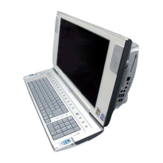
SERVICE MANUAL
SERVICE MANUAL
PCV-W Se
PCV
-W Series
American Area
American Area
Mexican Model
Mexican Model
Ver. 6-2007B
Ver. 6-2007B
Revision History
Revision History
Line up
Line up : PCV-W500M
: PCV-W500M
PCV-W600M
PCV-W600M
PCV-W700M
PCV-W700M
• • Des
Design an
ign and spec
d specifi ificati
cations ar
ons are subj
e subject t
change without notice.
change without notice.
2007B0500-1
2007B0500-1
©2007 Sony Corporation
©2007 Sony Corporation
Published by Sony Corporation VAIO Business Group VAIO Global CS Dept.
Published by Sony Corporation VAIO Business Group VAIO Global CS Dept.
TOP
TOP
FOR SAFETY
FOR SAFETY
ries
ect to o
DISASSEMBLY
DISASSEMBLY
FRAMEHARNESS
FRAMEHARNESS
( ( 17inch
17inch ) )
PCV-W500M
PCV-W500M
PARTS LIST
PARTS LIST
EXPLODED VIEW
EXPLODED VIEW
PERSONAL COMPUTER
PERSONAL COMPUTER
Advertisement
Table of Contents

Related Manuals for Sony VAIO PCV-W700M


Summarization of Contents
Safety Information
Lithium-Ion Battery Safety
Details warnings and instructions for the safe handling, use, and disposal of lithium-ion batteries.
Service and Inspection Safety Precautions
Essential guidelines for performing service and inspections safely and correctly.
Disassembly Procedures
Top (Cover) Assembly Removal
Procedure for removing the top cover assembly.
Memory Module Removal
Procedure for removing and installing the memory module.
Rear Cover Removal
Procedure for removing the main rear cover.
ANL-42 Board Removal
Procedure for removing the ANL-42 board.
HDD Removal
Procedure for removing the Hard Disk Drive (HDD).
I/O Panel Assembly and Hinge Cover Removal
Procedure for removing the I/O panel assembly and hinge cover.
Main Unit-1 Removal
Procedure for removing the first part of the main unit.
Main Unit-2 Removal
Procedure for removing the second part of the main unit.
DC Fan Removal
Procedure for removing the DC fan.
Mother Board Removal
Procedure for removing the mother board.
DC Fan with Heat Sink Removal
Procedure for removing the DC fan with heat sink.
CPU Removal and Installation
Procedure for removing and installing the CPU and heat sink.
Switching Power Supply Removal
Procedure for removing the switching power supply unit.
Front Unit Removal
Procedure for removing the front unit.
Rear Cover (LCD) Assembly Removal
Procedure for removing the rear cover (LCD) assembly.
Keyboard Unit Removal
Procedure for removing the keyboard unit.
CNX-217 Board and Inverter Unit Removal
Procedure for removing the CNX-217 board and inverter unit.
Speaker Unit Removal
Procedure for removing the speaker unit.
LEX-48 Board Removal
Procedure for removing the LEX-48 board.
LCD Unit Removal
Procedure for removing the LCD unit.
Optical Drive, Slimide Board-1 Removal
Procedure for removing the optical drive and Slimide board (1).
Optical Drive, Slimide Board-2 Removal
Procedure for removing the optical drive and Slimide board (2).
Optical Drive, Slimide Board-3 Removal
Procedure for removing the optical drive and Slimide board (3).
ANL-41 Board Removal
Procedure for removing the ANL-41 board.
Exploded Views and Part Identification
Rear Unit Exploded View
Exploded view of the rear unit components.
Main Unit Exploded View
Exploded view of the main unit components.
Front Unit-1 Exploded View
Exploded view of the front unit (part 1) components.
Front Unit-2 Exploded View
Exploded view of the front unit (part 2) components.
Tapes and Gaskets on LCD Chassis
Location diagram for tapes and gaskets on the LCD chassis assembly.
Accessories Exploded View
Exploded view of included accessories.
Service Parts List
Basic Parts List
List of standard service parts with part numbers and descriptions.
Substitution List
Alternative parts to order if primary parts are unavailable.
Accessories & Packing Materials List
List of accessories and packing materials included with the product.
Need help?
Do you have a question about the VAIO PCV-W700M and is the answer not in the manual?
Questions and answers