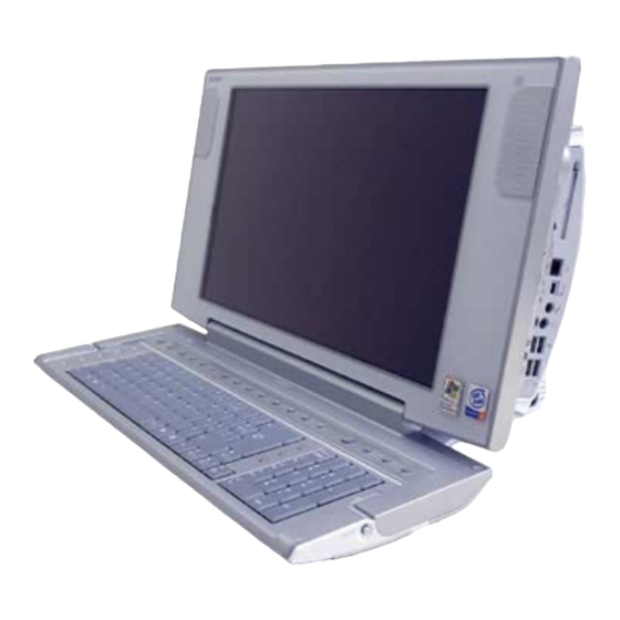
Sony VAIO PCV-W510G Service Manual
17 inch
Hide thumbs
Also See for VAIO PCV-W510G:
- Specifications (129 pages) ,
- Specifications (1 page) ,
- Supplementary manual (9 pages)
Table of Contents
Advertisement
Quick Links
SERVICE MANUAL
PCV-W Series
American Area
US Model
Canadian Model
Ver. 6-2005E
Revision History
Line up: PCV-W500GN1
PCV-W510G
PCV-W600G
PCV-W700G
• Design and specifications are subject to
change without notice.
2005E0500-1
©2005 Sony Corporation
Published by Sony EMCS NAGANO TEC
9-874-380-15
TOP
FOR SAFETY
DISASSEMBLY
FRAMEHARNESS
( 17inch )
PCV-W700G
PARTS LIST
EXPLODED VIEW
PERSONAL COMPUTER
Advertisement
Table of Contents

Related Manuals for Sony VAIO PCV-W510G


Summarization of Contents
FOR SAFETY
General Service Precautions
Essential safety guidelines for servicing and handling the equipment.
DISASSEMBLY
Disassembly Flowchart Overview
Overview of the disassembly process with a flowchart linking component removal steps.
TOP (COVER) ASSY
Procedure for removing the top cover assembly.
MEMORY MODULE
Procedure for removing the memory module.
REAR COVER
Procedure for removing the rear cover.
ANL-42 BOARD
Procedure for removing the ANL-42 board.
HDD
Procedure for removing the Hard Disk Drive (HDD).
IO (PANEL) ASSY, HINGE (COVER)
Procedure for removing the I/O panel assembly and hinge cover.
MAIN UNIT-1
Procedure for removing Main Unit 1.
MAIN UNIT-2
Procedure for removing Main Unit 2.
ENX-20/26 BOARD, RISER BOARD
Procedure for removing ENX-20/26 board and Riser board.
MOTHER BOARD
Procedure for removing the mother board.
DC FAN (WITH HEAT SINK)
Procedure for removing the DC fan with heat sink.
CPU
Procedure for removing the CPU.
SWITCHING POWER
Procedure for removing the switching power supply unit.
FRONT UNIT
Procedure for removing the front unit.
REAR COVER (LCD) ASSY
Procedure for removing the rear cover (LCD) assembly.
KEYBOARD UNIT
Procedure for removing the keyboard unit.
CNX-217 BOARD, INVERTER UNIT, RAY-CATCHER UNIT
Procedure for removing CNX-217 board, inverter, and ray-catcher.
SPEAKER UNIT
Procedure for removing the speaker unit.
LEX-48 BOARD
Procedure for removing the LEX-48 board.
LCD UNIT
Procedure for removing the LCD unit.
OPTICAL DRIVE, SLIMIDE BOARD-1
Procedure for removing optical drive and Slimide board 1.
OPTICAL DRIVE, SLIMIDE BOARD-2
Procedure for removing optical drive and Slimide board 2.
OPTICAL DRIVE, SLIMIDE BOARD-3
Procedure for removing optical drive and Slimide board 3.
ANL-41 BOARD
Procedure for removing the ANL-41 board.
EXPLODED VIEW
Rear Unit Exploded View
Exploded view of the rear unit components.
Main Unit Exploded View
Exploded view of the main unit components.
Front Unit Exploded Views
Exploded views of the front unit components.
LCD Chassis Tapes and Gaskets Location
Diagram showing placement of tapes and gaskets on the LCD chassis.
Accessories
Illustrations of included accessories like power cord, mouse, and remote.
PARTS LIST
Basic Parts List
The primary list of parts with part numbers and descriptions.
Substitution List
Alternative parts list for when primary parts are unavailable.
Accessories & Packing Materials
List of accessories and packing materials with part numbers.
Need help?
Do you have a question about the VAIO PCV-W510G and is the answer not in the manual?
Questions and answers