Table of Contents
Advertisement
Quick Links
Advertisement
Table of Contents

Summarization of Contents
1. INTRODUCTION
1.1. INTENDED USE
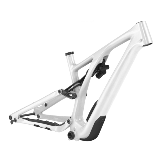
Specialized Stumpjumper Evo bicycles are intended for Mountain Bike (condition 4) use only.
1.2. WARRANTY
Information on written warranty provisions and how to visit www.specialized.com for details.
2. GENERAL NOTES ABOUT ASSEMBLY
2.1. FORK/HEADSET
Details on headset bearings, installation, and inspecting fork, stem, and seat tube for burrs.
2.2. SEATPOST
Explains minimum and maximum seatpost insertion requirements and torque specifications.
2.3. BOTTOM BRACKET
Information on the threaded 73mm bottom bracket shell and BSA compatibility.
2.4. REAR AXLE
Details on 148mm Boost hub spacing and the SRAM UDH derailleur hanger.
2.5. SEATSTAY
Explains different seatstay lengths for balanced weight distribution and consistent handling.
2.6. BULKHEAD AND DOWNTUBE PROTECTOR
Describes the downtube protector and its attachment via an internally mounted bulkhead.
2.7. STEM
Instructions for installing and torquing the stem, including warnings about gaps and sharp edges.
4. SPECIFICATIONS
4.1. GEOMETRY
A detailed table of frame geometry measurements for different sizes.
4.2. GENERAL SPECIFICATIONS
Lists part numbers and specifications for various components like headset, seat collar, and axle.
4.3. SHOCK CUSTOMIZATION
Guidance on working with suspension components and potential compatibility issues.
4.4. TOOLS REQUIRED
Lists necessary tools for assembly and maintenance.
4.5. BOLT SIZE / TOOLS / TO TORQUE SPECIFICATIONS
General information and warnings about fastener tightening and torque specifications.
4.6. GENERAL TORQUE SPECIFICATIONS
A table detailing torque specifications for various bike components.
4.7. BEARING SPECIFICATIONS
Details on bearing types and dimensions for pivot locations.
4.8. SPACER/AXLE/BOLT SPECIFICATIONS
Lists specifications for various spacers, axles, and bolts used in assembly.
5. INTERNAL ROUTING
5.1. DROPPER SEATPOST
Instructions for routing the dropper seatpost housing through the frame.
5.2. INTERNAL GUIDE TUBES
Steps and tips for preparing and installing internal guide tubes before routing.
5.3. SHIFT/BRAKE HOUSING
Instructions for routing shift and brake housings through the frame, including rear brake details.
5.4. HEAD TUBE ICR PORT
Explains how to route cables through the head tube ports using rubber plugs.
6. REAR TRIANGLE PIVOT ASSEMBLY
6.1. BEARING ASSEMBLY
Visual guide and instructions for installing main pivot and link bearings and spacers.
6.2. PIVOT ASSEMBLY
Instructions for assembling the extension to shock and link to seat tube pivots.
7. FLIP CHIPS
7.1. ADJUSTING THE HORST PIVOT FLIP CHIP
Instructions for adjusting the Horst pivot flip chips to change geometry.
7.2. ADJUSTING THE HEADTUBE ANGLE
Instructions for adjusting the headtube angle using adjustable headset cups.
8. AIR SHOCK SETUP
8.1. SETTING AIR PRESSURE
Steps to set the air pressure in the shock, including checking sag.
8.2. ADJUSTING REBOUND
Guidance on adjusting the rebound damping knob for shock return rate.
8.3. ADJUSTING COMPRESSION
Explains how to adjust compression damping for shock platform support.


Need help?
Do you have a question about the EVO S4 and is the answer not in the manual?
Questions and answers