Advertisement
Quick Links
Download this manual
See also:
Manual
SERVICE MANUAL
MODEL TYPE: YS1061
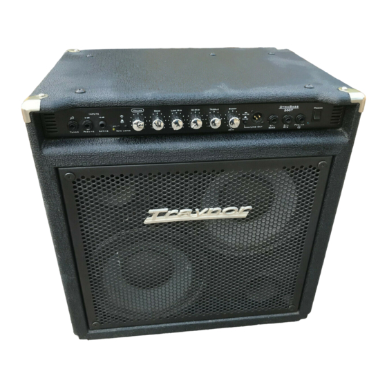
DynaBass 200 & 200T
WEB ACCESS: http://www.yorkville.com
WORLD HEADQUARTERS
CANADA
U.S.A.
Yorkville Sound
Yorkville Sound Inc.
550 Granite Court
4625 Witmer Industrial Estate
Pickering, Ontario
Niagara Falls, New York
L1W-3Y8 CANADA
14305 USA
Voice: (905) 837-8481
Voice: (716) 297-2920
Fax: (905) 837-8746
Fax: (716) 297-3689
Quality and Innovation Since 1963
Printed in Canada
Manual-Service-DB200-DB200T-00-1v2
Advertisement

Related Manuals for Traynor DYNABASS 200 - MANUAL SERVICE


Summary of Contents for Traynor DYNABASS 200 - MANUAL SERVICE
- Page 1 SERVICE MANUAL MODEL TYPE: YS1061 DynaBass 200 & 200T WEB ACCESS: http://www.yorkville.com WORLD HEADQUARTERS CANADA U.S.A. Yorkville Sound Yorkville Sound Inc. 550 Granite Court 4625 Witmer Industrial Estate Pickering, Ontario Niagara Falls, New York L1W-3Y8 CANADA 14305 USA Voice: (905) 837-8481 Voice: (716) 297-2920 Fax: (905) 837-8746 Fax: (716) 297-3689...
-
Page 2: Important Safety Instructions
IMPORTANT SAFETY INSTRUCTIONS This lightning flash with arrowhead symbol, The exclamation point within an equilatereal within an equilateral triangle, is intended to alert triangle is intended to alert the user to the the user to the presence of uninsulated presence of important operating and “dangerous voltage”... - Page 3 Block Diagram for DynaBass 200/200T D E S I G N E D A N D M A N U F A C T U R E D B Y Y O R K V I L L E S O U N D MODEL TYPE: YS1061 Speaker, Line &...
- Page 4 8' 3/18 SJT AC LINE CORD REMOVABLE 8734 #10 X 1/2 PAN PH TYP A BRITE NICKEL 6822 1N4745A 16V0 1W0 ZENER 5% T&R 8268 TRAYNOR LOGO PLASTIC NICKEL PLATING 8749 10-32 X 1/2 QDX PH TAPTITE JS500 5101 BC550C TO92 NPN TRAN T&R TB 3538 24 PIN BREAKAWAY LOCK .156...
- Page 5 Labeled Components 7417 _8R 30W TWEETER PIEZO TLC 1 7347 15" 4R 200WPGM SPEAKER BASS Z891* DB200 GRILLE TRAYNOR LOGO PLASTIC NICKEL PLA 8268 8504 CORNER, 2 LEGS NOTCED LIP NICKE 8599 2" CASTOR AND SOCKET 3428 / 8' 3/18 SJT AC LINE CORD REMOVA...
- Page 6 +FOPV +15V 100V 100P 100N 100N 100N 100N 100N 100N U5:C U1:E U2:C U3:C U4:C U6:C U7:C 1/4W BASS 1/4W _FOPV TL072 HI-MID -15V 1/4W 1/4W P5:A 1/4W 1/4W B LIN 4420 100N 100N 100N 100N 10K0 EFX SEND P6:A TL072 1/4W 100N...
- Page 7 3425 S2:A LIMITER SW R104 R135 R155 BC550C 1/4W 1/4W 1/4W +15V 220K 470R R103 BC560C 470R +15V 5101 R156 1/4W U8:B R126 TO92 6880 5102 4N35 TO92 5102 BC560C TO92 R159 1/4W TO-LIMITER 100K R102 1/4W R157 -15V 1/4W MC33078P R176 1/4W...
- Page 8 POWER #3409 BlankSize - 18000x9000 ETCH GUIDE TO W27 M1326 NET00096 ETCH 9" RED TWEETER DEFEAT GUIDE 3498 3417 3417 NET00034 9" RED Into Wave TO TWEETER TO SWITCH FROM AMP Top Assy X1009 2V01 ETCH Pcb Mech X1009 2V01 GUIDE FROM SWITCH EXT-SPKR...
- Page 9 SEE LAYOUT DIAGRAM M1326 PRODUCTION NOTES FUSE N/A 2.5 A /120 V (2407) CE 1.6 A / 230 V (2473) W1 = GREEN 6" 1 ADD THERMAL JOINT COMPOUND(GOOP) BETWEEN Q8 AND Q11; W2 = RED 9" Q7 AND Q13. COVER WITH VINYL CAP (8609) AND RTV. W6 AND W13 = RED 19"...
-
Page 10: Pin Configuration
SEE LAYOUT DIAGRAM M1326 - M1327 - X1009 HISTORY M1326 - M1327 POTS LIST MODEL(S):- DB200/T MODEL(S):- DB200/T PIN CONFIGURATION DATE VER# DESCRIPTION OF CHANGE FUNCTION PART# KNOB {NEW} SEP-13-2006 1.00 DERIVED FROM M633 V4.00 VOLUME 4418 8399 JUL-05-2007 CORRECTED T0-3 DIAGRAM, R74 -> #2042 FUSIBLE, R82-> 4420 8399 MJ21196... - Page 11 8' 3/18 SJT AC LINE CORD REMOVABLE 8722 #8 X 1" PAN QUAD TYPE AB B/O 5122 J109 TO92 NCH JFET T&R TC 8268 TRAYNOR LOGO PLASTIC NICKEL PLATING 8734 #10 X 1/2 PAN PH TYP A BRITE NICKEL 6787 BD237 TO126 NPN TRAN 3538 24 PIN BREAKAWAY LOCK .156...
- Page 12 POWER #3409 BlankSize - 18000x9000 ETCH GUIDE TO W27 M1327 NET00096 ETCH 9" RED TWEETER DEFEAT GUIDE 3498 3417 3417 NET00034 9" RED Into Wave TO TWEETER TO SWITCH FROM AMP Top Assy X1009 2V00 ETCH Pcb Mech X1009 2V00 GUIDE FROM SWITCH EXT-SPKR...
- Page 13 SEE LAYOUT DIAGRAM M1327 PRODUCTION NOTES FUSE N/A 2.5 A /120 V (2407) CE 1.6 A / 230 V (2473) W1 = GREEN 6" 1 ADD THERMAL JOINT COMPOUND(GOOP) BETWEEN Q8 AND Q11; W2 = RED 9" Q7 AND Q13. COVER WITH VINYL CAP (8609) AND RTV. W6 AND W13 = RED 19"...
- Page 14 SEE LAYOUT DIAGRAM M1326 - M1327 - X1009 HISTORY M1326 - M1327 POTS LIST MODEL(S):- DB200/T DB200/T PIN CONFIGURATION MODEL(S):- DATE VER# DESCRIPTION OF CHANGE FUNCTION PART# KNOB {NEW} SEP-13-2006 1.00 DERIVED FROM M633 V4.00 VOLUME 4418 8399 JUL-05-2007 CORRECTED T0-3 DIAGRAM, R74 -> #2042 FUSIBLE, R82-> 4420 8399 MJ21196...
Need help?
Do you have a question about the DYNABASS 200 - MANUAL SERVICE and is the answer not in the manual?
Questions and answers
THE LIGHT DOES NOT COME ON WHEN TURNING THE SWITCH ON. TOTALLY DEATH
The Traynor DYNABASS 200 may not power on when the switch is turned on due to the following possible causes:
1. Blown fuse: The fuse may be blown. The manual specifies a 2.5A/120V fuse for North America and a 1.6A/230V fuse for Europe. If the fuse is damaged, the unit will not power on.
2. Power cord or connection issue: The power cord could be faulty or not properly connected.
3. Faulty power switch: The switch labeled "SWITCH LEY F1" may be defective or not making proper contact.
4. Internal wiring issue: Internal wires such as W1 (green), W2 (red), or others might be disconnected or damaged.
5. Component failure: Components like Q8, Q11, Q7, or Q13 may have failed. These are mentioned with thermal compound and vinyl cap instructions, indicating they are part of the power section.
6. No thermal compound: Missing thermal compound between Q8 and Q11, or improper assembly, could cause overheating or poor conduction, leading to failure.
7. Incorrect fuse rating: Using the wrong fuse type or rating could prevent operation or cause immediate failure.
Inspecting these areas can help identify the cause of the power issue.
This answer is automatically generated