Table of Contents
Advertisement
SERVICE MANUAL
Ver. 1.0 2017.05
• All the units included in the HT-RT4/RT40
(SA-WRT4/WRT40, SS-RT4/SRT4, remote
control) are required to confi rm the operation
of SA-WRT4/WRT40. Check in advance that
you have all the units.
Note:
Be sure to keep your PC used for service and
checking of this unit always updated with the
latest version of your anti-virus software.
In case a virus affected unit was found during
service, contact your Service Headquarters.
COMPONENT MODEL NAME
Bar Speaker (Speaker System)
Surround Speaker (Speaker System)
Subwoofer (Active Subwoofer)
• The service manual for SS-RT4/SRT4 has been issued separately.
Please refer to the service manual for information.
Amplifi er section
POWER OUTPUT (rated)
Front L + Front R:
35 W + 35 W (at 2.5 ohms, 1 kHz,
1% THD)
POWER OUTPUT (reference)
Front L/Front R/Surround L/
Surround R:
65 W (per channel at 2.5 ohms,
1 kHz)
Center:
170 W (at 4 ohms, 1 kHz)
Subwoofer:
170 W (at 4 ohms, 1 kHz)
Inputs
USB
ANALOG IN
TV IN (OPTICAL)
Output
HDMI OUT (ARC)
HDMI section
Connector
Type A (19pin)
USB section
(USB) port
Type A
BLUETOOTH section
Communication system
BLUETOOTH Specifi cation
version 4.2
Output
BLUETOOTH Specifi cation
Power Class 1
Maximum communication range
Line of sight approx. 25 m
1)
9-890-690-01
Sony Corporation
2017E81-1
©
2017.05
Published by Sony EMCS (Malaysia) PG Tec
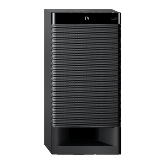
Photo: HT-RT4
HT-RT4
HT-RT40
SS-RT4
SS-RT4
SS-SRT4
SS-SRT4
SA-WRT4
SA-WRT40
SPECIFICATIONS
Frequency band
2.4 GHz band (2.4000 GHz –
2.4835 GHz)
Modulation method
FHSS (Freq Hopping Spread
Spectrum)
Compatible BLUETOOTH profi les
2)
A2DP 1.2 (Advanced Audio
Distribution Profi le)
AVRCP 1.6 (Audio Video Remote
Control Profi le)
Supported Codecs
3)
SBC
4)
, AAC
5)
Transmission range (A2DP)
20 Hz – 20,000 Hz (Sampling
frequency 32 kHz, 44.1 kHz,
48 kHz)
The actual range will vary depending
1)
on factors such as obstacles between
devices, magnetic fi elds around a
microwave oven, static electricity,
cordless phone, reception sensitivity,
antenna's performance, operating
system, software application, etc.
BLUETOOTH standard profi les
2)
indicate the purpose of BLUETOOTH
communication between devices.
3)
Codec: Audio signal compression and
conversion format
Subband Codec
4)
5)
Advanced Audio Coding
HT-RT4/RT40
Speaker section
Speaker system
Subwoofer system, Bass refl ex
Speaker
160 mm cone type
General
Power requirements
LA9 models only:
110 V - 240 V AC, 50/60 Hz
EA models only:
127 V – 240 V AC, 50/60 Hz
Except LA9, EA models:
220 V – 240 V AC, 50/60 Hz
Power consumption
On: 85 W
Standby: 0.5 W or less (Power
saving mode)
(When "CTRL" in "HDMI>" and
"BTSTB" in "BT >" are set to
"OFF")
Standby: 2.8 W or less
6)
(When "CTRL" in "HDMI>"
or "BTSTB" in "BT >" is set to
"ON")
Dimensions (w/h/d) (approx.)
190 mm × 392 mm × 315 mm
Mass (approx.)
7.8 kg
HOME THEATRE SYSTEM
ACTIVE SUBWOOFER
SA-WRT4/WRT40
AEP Model
UK Model
HT-RT4
E Model
Australian Model
HT-RT40
The system will automatically enter
6)
Power saving mode when there is
no HDMI connection and no BLUE-
TOOTH pairing history, regardless
of the settings you have made for
"CTRL" in "HDMI>" and "BTSTB"
in "BT >".
Supplied accessories
Remote control (1)
R03 (size AAA) batteries (2)
High Speed HDMI cable (1) (HT-RT40)
Optical digital cable (1) (HT-RT4)
Speaker bases (2)
Screws (8)
AC plug adaptor (1) (HT-RT40: LA9)
Design and specifi cations are subject to
change without notice.
HT-RT4/RT40
SA-WRT4/WRT40
Advertisement
Table of Contents

Related Manuals for Sony SA-WRT4


Summarization of Contents
Servicing Notes and Precautions
Unleaded Solder Properties
Details characteristics and handling of unleaded solder for repairs.
Service Preparation and Operation Checks
Covers pre-service checks, operation confirmation, and display message handling.
Component Replacement Guidelines
Notes for replacing specific ICs, the heat sink compound, and Bluetooth modules.
Disassembly Procedures
Disassembly Flowchart
Step-by-step guide for disassembling the unit.
Front Panel Section 1 Removal
Procedure for removing the first part of the front panel.
Front Panel Section 2 Reassembly
Procedure for reassembling the second part of the front panel.
Loudspeaker Removal
Instructions for removing the 16cm loudspeaker unit.
Chassis and Bluetooth Module Removal
Steps for removing the chassis section and Bluetooth module.
Speaker CHUKEI PC Board Removal
Procedure for removing the speaker CHUKEI PC board.
Main Board and Regulator Removal
Procedure for removing the main board, connector board, and regulator.
System Test Modes
Reset, Panel, and Version Tests
Covers Cold Reset, Panel Test, Software Version Check, and Amp Test procedures.
Demo and USB Update Test Modes
Guides for performing Demo Mode and USB Update Test Mode.
Troubleshooting Guide
'PRTCT' Display Errors
Diagnosing and resolving 'PRTCT' display messages on the OLED.
HDMI Video Display Issues
Troubleshooting no video output during HDMI connection in USB mode.
No Sound Output Diagnosis
Steps to identify and fix sound output problems.
Power On Failure Troubleshooting
Diagnosing and resolving issues when the unit does not power on.
USB Detection Failure
Steps to troubleshoot when the USB device is not detected.
Circuit Diagrams and Layouts
Block Diagrams
Main Control, Audio, and Power Supply block diagrams.
Main Board Printed Wiring Diagram
Printed wiring layout for the Main (RT4) / EG4 Main (RT40) board.
EG4 OLED CHUKEI PC Board Diagrams
Printed wiring and schematic diagrams for the EG4 OLED CHUKEI PC board.
Touch Board Diagrams
Printed wiring and schematic diagrams for the Touch board.
Speaker CHUKEI PC Board Diagrams
Printed wiring and schematic diagrams for the Speaker CHUKEI PC board.
Connector and USB Board Diagrams
Wiring and schematic diagrams for Connector and USB boards.
Exploded Views and Parts
Overall Assembly Exploded View
Exploded diagram of the complete unit assembly.
Chassis Assembly Exploded View
Exploded diagram showing chassis components.
Main Board Assembly Exploded View
Exploded diagram of the main board section.
Need help?
Do you have a question about the SA-WRT4 and is the answer not in the manual?
Questions and answers