Table of Contents
Advertisement
https://appliancetechmanuals.com
MODEL NAME : RF31FM** / RF24FS**
MODEL CODE :
RF31FMESBSR/AA RF31FMESBSL/SA
RF31FMEDBSR/AA RF31FMEDBBC/AA
RF31FMEDBWW/AA RF31FMEDBSL/ML
RF31FMEDBSL/HC RF24FSEDBSR/AA
RF24FSEDBSR/EU
RF24FSEDBBC/EU
RF24FSEDBSL/SA
2013. 02
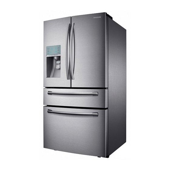
SAMSUNG French Door Refrigerator
AW4-4D PJT
New product training for refrigerator
RF24FSEDBSR/EF
RF24FSEDBSR/WT
RF24FSEDBX3/SC
Advertisement
Table of Contents

Summarization of Contents
Precautions and Safety Warnings
General Safety Precautions
General safety guidelines for appliance operation and maintenance.
Warning Symbols Explained
Explanation of warning and caution symbols used in the manual.
Operational Safety Guidelines
Safety rules for replacing parts, wiring, and handling electrical components.
Installation and Usage Precautions
Safety advice regarding installation, grounding, and proper usage.
Product Specifications
Introduction to Main Functions
Overview of key features like Surround Multi Flow, Twin Cooling, and Flex Zone.
Interior Views
Labeled diagrams of the refrigerator and freezer interiors for different models.
Model Specification Chart
Detailed specifications including external size, capacity, weight, and components.
Refrigeration Cycle Information
Description of the refrigerant flow path in the refrigeration cycle.
Component Specifications
Operational theory of refrigeration cycle components like condenser, capillary, and compressor.
Dimensions
Dimensional drawings and measurements for RF31FM** and RF24** models.
Optional Material Specification
List of optional parts with part codes and quantities.
Instruction of Function
Digital Display Functions
Explanation of all buttons and indicators on the refrigerator's digital control panel.
Disassembly and Assembly
General Disassembly Precautions and Tools
Safety guidelines and required tools for disassembly and assembly procedures.
Door and Handle Assembly/Disassembly
Steps for removing refrigerator doors, handles, and related hardware.
Internal Component Disassembly
Procedures for removing filters, shelves, drawers, and carbonator kits.
Key Component Disassembly (Ice Maker, Fan, Lights, Switches)
Steps for disassembling ice makers, fan motors, lights, and door switches.
Major Component Disassembly (Compressor, Electric Box)
Procedures for disassembling the compressor and electric box components.
CO2 Cylinder Installation and Precautions
Guide for installing and handling CO2 cylinders for the sparkling water feature.
Check the installation status
Failure Diagnosis Functions
Overview of failure diagnosis modes including test mode and manual operation.
Diagnostic Methods (Flow Chart)
Flowcharts and tables for diagnosing troubles based on symptoms and sensor readings.
Self Diagnosis & Trouble Shooting
Sensor Error Troubleshooting
Detailed steps for troubleshooting various sensor errors (ICE Maker, R, DEF, Ambient, F, Humidity).
Fan Operation Troubleshooting
Troubleshooting steps for when the refrigerator fans are not operating.
Ice Maker, Defrost, and Power Troubleshooting
Troubleshooting for ICE Maker issues and defrost system problems.
Compressor, Alarm, and Panel Troubleshooting
Steps for diagnosing compressor, alarm, and panel operation faults.
Pantry PCB, Lamp, and Water Supply Troubleshooting
Troubleshooting steps for pantry PCB, refrigerator lamp, and ice water supply.
Sparkling System and Ice Dispensing Troubleshooting
Troubleshooting for sparkling water and ice dispensing issues.
Motor, Sensor, and General Diagnosis
Troubleshooting for ice route motors, IR sensors, and general operational problems.
PCB DIAGRAM
PCB Layouts and Connector Locations
Diagrams showing PCB layouts and connector positions for main and inverter boards.
Wiring diagram
Wiring Diagram (All Models and Sparkling Model)
Wiring diagrams for common models and specific sparkling water models.
SCHEMATIC DIAGRAM
Whole Block Diagrams
High-level block diagrams illustrating system architecture for RF31FM** and RF24FS** models.
MODEL CODE TABLE
Nomenclature Explanation
Explanation of the model code structure for RF31FM** and RF24FS** series.


Need help?
Do you have a question about the MKV190CL2B/E01 and is the answer not in the manual?
Questions and answers