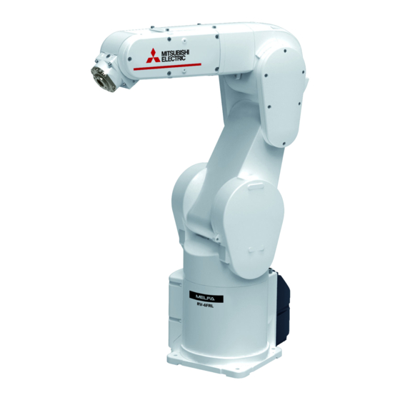
Summarization of Contents
FUNCTIONS AND CONFIGURATION
1.1 Overview
General overview of safety communication and monitoring functions.
1.2 Supported Products
Lists compatible robot controllers and network requirements.
1.3 System Configuration
Explains system architecture for safety communication using master/local modules.
1.4 Specifications
Details safety functions, communication, and performance specifications.
1.5 Risk Assessment
Discusses risk assessment for safety monitoring functions and residual risks.
SET-UP
System Construction and Network Settings
Guides system setup, network configuration, and communication destination settings.
Robot Controller Safety Monitoring Function Settings
Outlines configuration of safety monitoring functions on the robot controller.
CONNECTIONS AND COMMUNICATION DESTINATION SETTINGS
3.1 System Configurations and Connections
Details system architecture and connections between controllers and safety devices.
3.2 Network Communication Settings
Covers parameter settings for CC-Link IE TSN master/local stations.
3.3 Safety Communication Settings (Safety Programmable Controller Side)
Explains safety communication parameter configuration on the safety programmable controller.
3.4 Creating a Safety Program
Guides the creation of a safety control program for the safety CPU module.
SAFETY MONITORING FUNCTIONS
4.1 Overview of Safety Monitoring Functions
Lists safety monitoring functions implementable with safety communication.
4.2 Startup and Basic Configuration
Details enabling functions, parameter configuration, and password settings.
4.3 Defining 3D Models
Covers defining shape models for robot arm and tools for safety monitoring.
4.4 Safety Logic Edit
Explains setting safety logic for monitoring functions using safety I/O.
4.5 Safety Monitoring Functions
Provides overview and configuration for STO, SOS, SS1, SS2, SLS, and SLP functions.
4.6 Safety Diagnosis Function
Details test pulse diagnosis for confirming emergency stop line operation.
4.7 Safety Communication Function
Explains communication with external safety devices and connection status.
ROBOT (SYSTEM) STATE VARIABLES
5.1 List of Robot (System) State Variables
Tabulates state variables related to safety communication and monitoring.
5.2 Explanations of Robot (System) State Variables
Provides detailed explanations of key state variables.
TROUBLESHOOTING
6.1 Error List for the Safety Monitoring Functions
Lists error numbers, causes, and solutions for safety monitoring functions.
6.2 Errors Whose Specification Is Changed by Safety Monitoring Functions
Identifies errors whose behavior is modified when safety monitoring is active.
SAFETY RESPONSE TIME AND SAFE STOPPING DISTANCE
7.1 Safety Response Time
Defines safety response time calculation and components.
7.2 How to Calculate a Stopping Distance
Explains how to calculate maximum stopping distance based on various parameters.
7.3 Maximum Stopping Time and Maximum Operating Angle
Provides tables for maximum stopping time and angles across robot models.
7.4 Calculating stopping distance and stopping time
Details how to calculate stopping distance and time using oscillograph function.
SYSTEM APPLICATION EXAMPLES
8.1 Application Example 1
Demonstrates a system with one robot, human presence detection, and speed monitoring.
8.2 Application Example 2
Shows a system with multiple robots and safety sensors for human presence detection.


Need help?
Do you have a question about the R16 and is the answer not in the manual?
Questions and answers