Table of Contents
Advertisement
SERVICE MANUAL
Ver 1.1 2001.08
Sony Corporation
9-925-682-12
2001H0500-1
e Vehicle Company
C 2001.8
Shinagawa Tec Service Manual Production Group
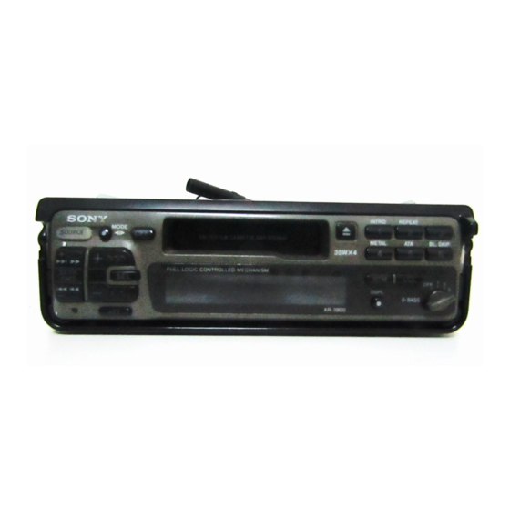
XR-2800/2803
Photo: XR-2800
Model Name Using Similar Mechanism
Tape Transport Mechanism Type
SPECIFICATIONS
FM/MW/LW CASSETTE CAR STEREO
AEP Model
UK Model
East European Model
MG-25E-136
XR-2800
XR-2803
NEW
Advertisement
Table of Contents

Related Manuals for Sony XR-2803


Summarization of Contents
Specifications Overview
Cassette Player Specifications
Details about tape playback performance parameters including wow/flutter and frequency response.
Tuner Specifications
Technical details for FM and AM reception, covering tuning range, sensitivity, and selectivity.
Power Amplifier Specifications
Output power and impedance ratings for the amplifier section, including speaker requirements.
General Specifications
Power requirements, dimensions, and supplied accessories for the unit.
Safety and Handling Precautions
Battery Replacement Warnings
Cautionary notes regarding battery replacement safety, explosion risks, and proper disposal.
General Information and Controls
Control Panel Layout
Identifies and describes the function of each control on the front panel.
Installation Guide
Installation Precautions
Guidelines for choosing an installation location and using mounting hardware safely.
Mounting Angle and Example
Instructions for adjusting the mounting angle and visual examples of installation.
Connection Notes and Removal Caution
Important notes for wiring and a caution for unit removal due to heat.
Electrical Connections
General Connection Cautions
Important safety and connection guidelines for the 12V DC system, including power leads.
Reset and Control Lead Notes
Instructions for using the reset button and notes on power antenna and control leads.
Memory Hold and Speaker Connection
Details on memory circuit power and guidelines for connecting speakers to avoid damage.
Disassembly Procedure
Cover Removal
Steps for removing the unit's outer cover using screws and clips.
Collar and Handle Assembly Removal
Steps for detaching the collar and handle assembly, involving screws and claws.
Mechanism Deck Assembly
Housing Assembly Steps
Detailed steps for assembling the housing components using projections and claws.
Arm (Suction) Assembly
Instructions for fitting the suction arm assembly onto the shaft and projection.
Adjustments
Mechanical Adjustments
Procedures for cleaning parts, demagnetizing, and torque measurement for mechanical adjustments.
Electrical Adjustments - Test Mode
How to enter and exit the service test mode for easier electrical adjustments.
Tape Speed Adjustment
Steps to adjust tape speed using a speed checker or frequency counter.
Tuner Section Adjustments
Procedures for adjusting FM auto scan/stop level and stereo separation.
AM (MW) Auto Scan/Stop Level Adjustment
Steps to adjust AM auto scan/stop level settings for the tuner.
Diagrams and IC Information
Main Board IC Block Diagrams
Block diagrams for integrated circuits on the main board.
Main Section Printed Wiring Boards
Layout of components and traces on the main printed circuit board.
Panel Section Schematics and Wiring
Printed wiring and schematic diagrams for the panel section.
IC Pin Function Descriptions
IC501 (System Controller) Pin Functions
Detailed pin functions for the main system controller IC501 (uPD17707GC-529-3B9).
Exploded Views
Chassis Section Exploded View
Illustrated breakdown of the chassis and related components.
Front Panel Section Exploded View
Illustrated breakdown of the front panel assembly and its parts.
Mechanism Deck Section Exploded View
Illustrated breakdown of the mechanism deck (MG-25E-136).
Electrical Parts List
Control Board Components
List of electronic components for the control board, including resistors and capacitors.
Main Board Components
Detailed list of components for the main board, covering resistors, capacitors, and ICs.
Power Board Components
List of components for the power board, including resistors, capacitors, and diodes.
Miscellaneous and Hardware Parts
Lists miscellaneous items, hardware, and accessories like cords and fuses.
Need help?
Do you have a question about the XR-2803 and is the answer not in the manual?
Questions and answers