Sign In
Upload
Download
Table of Contents
Contents
Add to my manuals
Delete from my manuals
Share
URL of this page:
HTML Link:
Bookmark this page
Add
Manual will be automatically added to "My Manuals"
Print this page
×
Bookmark added
×
Added to my manuals
Manuals
Brands
Gardner Denver Manuals
Air Compressor
ST75-100G2A
Operating and service manual
Gardner Denver ST75-100G2A Operating And Service Manual
Hide thumbs
1
2
3
4
5
Table Of Contents
6
7
8
9
10
11
12
13
14
15
16
17
18
19
20
21
22
23
24
25
26
27
28
29
30
31
32
33
34
35
36
37
38
39
40
41
42
43
44
45
46
47
48
49
50
51
52
53
54
55
56
57
58
59
60
61
62
63
64
65
66
67
68
69
70
71
72
73
74
75
76
77
78
79
80
81
82
83
84
85
86
87
88
89
90
91
92
93
94
95
96
97
98
99
100
page
of
100
Go
/
100
Contents
Table of Contents
Bookmarks
Table of Contents
Support Services
Instructions for Ordering Repair Parts/Remanufactured Airends
Warning - Prohibition - Mandatory Label Information
Safety Precautions
Table of Contents
Index
List of Illustrations
Section 1, General Information
Air Flow in the Compressor System
Compression Principle
Compressor
Figure 1-1 - Compression Cycle
Cooling, Sealing and Lubrication
Figure 1-2 - Starter Box
Figure 1-3 - Control Box
Figure 1-4 - Compressor / Motor Side
Figure 1-5 - Cooler / Reservoir Side
Figure 1-6 - Air/Oil Flow Diagram
Section 2, Installation
Lifting Unit
Location
Air-Cooled Units, Location
Air-Cooled Units
Figure 2-1 - Typical Compressor Room
Figure 2-2 - Air Flow Chart
Foundation
Water-Cooled Units
Drain
Cold Weather Operation
Cold Weather Operation, Installation for
Installation for Cold Weather Operation
Figure 2-3 - Cold Weather Installation
Auxiliary Air Receiver
Control Piping
Inlet Line
Moisture Separator/Trap
Figure 2-4 - Inlet Line Lengths
Blowdown Valve Piping
Figure 2 5 - Heat Exchanger (Oil Cooler) Approximate Water Flow
Water Piping
Figure 2-6 - Aftercooler Approximate Water Flow
Water Piping (Series)
Figure 2-7 - Series Piping
Figure 2-8 - Parallel Piping
Electrical Wiring
Grounding
Water Piping (Parallel)
Lubrication Motor
Section 3, Starting & Operating Procedures
Prestart-Up Instructions
Daily Check
Starting the Unit
Unit Cold
Unit Hot
Stopping the Unit
Quick Start Guide (Controller)
Section 4, Controls & Instrumentation
Controls & Instrumentation Airsmart G2 Controller Operation
General Description
Figure 4-1 - Controller Keypad
Figure 4- 2- Schematic Tubing Diagram
Blowdown Valve
Minimum Discharge Pressure Valve
Figure 4- 3- Minimum Discharge Pressure/Check Valve
Inlet Valve
Pressure Regulator
Shuttle Valve
Solenoid Valves IVC and IVO
Air Filter Vacuum Switch
Plant Delivery
Reservoir
Separator
Figure 4-4 -Turn Valve - Electra Saver Only
Emergency Stop Push-Button
Temperature Sensor Discharge
Separator
Fan Starter
Fuse Blocks
Main Starter
Power Supply
Terminal Strip
Figure 4- 5- Compressor Package P&ID
Figure 4- 6- Compressor Package Control Component States
Figure 4- 7- Electra Saver Wiring Diagrams
Figure 4- 8- Electra Saver II Wiring Diagrams
Figure 4- 9- Wiring Diagram - WYE DELTA (AIR-COOLED / WATER-COOLED)
Figure 4- 10- Wiring Diagram - WYE DELTA (AIR-COOLED / WATER-COOLED)
Section 5, Lubrication, Oil Cooler, Oil Filter & Separator
Lubricant Recommended
Oil Specifications
Oil System Compressor
High Temperature Operation
Moisture in the Oil System
Figure 5-1 - Dew Point Chart F
Figure 5-2 - Dew Point Chart C
Figure 5-3 - Flow Diagram - Air/Oil System
Figure 5-4 - Oil Flow Diagram - Remote Overhead Mounted Cooler
Remote Mounted Elevated Cooler Assembly
Heat Exchanger (Oil) Piping
Addition of Oil between Changes
Cold Ambient Operation
Lubricant Change Procedure
Oil Change Interval
Oil Level Gauge
Figure 5-5 - Oil Level Gauge
Oil Sampling Valve
Figure 5-6 - Oil Change Interval
Figure 5-7 - Oil Sampling Valve Location
Draining and Cleaning
Filling
Figure 5-8 - Approximate Oil System Capacities
Oil Filter
Compressor Oil Cooler - Water-Cooled Heat Exchanger
Oil Cooler - Radiator Type
Thermal Control (Thermostatic Mixing) Valve
Figure 5-9 - Thermostatic Mixing Valve Element
Figure 5-10 - Water Control Valve
Water Flow Control Valve for Heat Exchanger
Oil Reservoir
Oil Separator Compressor (GD Eliminator)
Oil Carryover
Water Shutoff Valve - Water-Cooled Heat Exchanger
Figure 5-11 - Oil Separator
Inspection
Pressure Differential Gauging
Removal for Inspection or Replacement
Oil System Check
Air and Oil Discharge Temperature
Oil Inlet Pressure
Oil Inlet Temperature
Oil Cooler Oil Pressure Differential (Air-Cooled Radiator)
Oil Cooler Oil Pressure Differential (Water-Cooled Heat Exchanger)
Oil Cooler Temperature Differential (Air-Cooled Radiator)
Oil Cooler Temperature Differential (Water-Cooled Heat Exchanger)
Oil Cooler Water Pressure Differential (Water-Cooled Heat Exchanger)
Section 6, Air Filter
Air Filter, Heavy Duty (Standard)
Filter Element
Figure 6-1 - Heavy Duty Air Filter
Air Filter Element Life
Inlet Tube
Section 7, Coupling
Coupling
Figure 7-1 - Installation of Coupling Cushions
Figure 7-2 - Installation of Coupling Cushions
Section 8, Maintenance Schedule
Service Check List
Every 1000 Hours Operation
Every 125 Hours Operation
Every 8 Hours Operation
Every 2000 Hours Operation
Service Check List
Section 9, Troubleshooting
Advertisement
Quick Links
1
Section 8, Maintenance Schedule
2
Section 9, Troubleshooting
Download this manual
13-21-611
Version: 00
January 7, 2019
ELECTRA-SAVER G2 &
ELECTRA-SAVER II G2
STATIONARY BASE-MOUNTED
COMPRESSOR
™
AirSmart
G2 Controller
CONFIGURATOR
SAV75-100G2A - 75, 100 HP
ST75-100G2A - 75, 100 HP
OPERATING AND
SERVICE MANUAL
Table of
Contents
Previous
Page
Next
Page
1
2
3
4
5
Advertisement
Table of Contents
Need help?
Do you have a question about the ST75-100G2A and is the answer not in the manual?
Ask a question
Questions and answers
Related Manuals for Gardner Denver ST75-100G2A
Air Compressor Gardner Denver Wittig SLS 34 Operating Manual And Spare Parts List
(26 pages)
Air Compressor Gardner Denver ELECTRA-SAVER G2 Operating And Service Manual
(100 pages)
Air Compressor Gardner Denver SAVG2-75 Installation, Operating & Service Manual
(84 pages)
Air Compressor Gardner Denver THOMAS SK927 Quick Start Manual
(2 pages)
Air Compressor Gardner Denver ESM 30 Original User Manual
Screw air compressor (61 pages)
Air Compressor Gardner Denver GD150 Service Manual
Rotaryvane compressor (28 pages)
Air Compressor Gardner Denver Electra-Screw EDEQHF Operating And Service Manual
Stationary base-mounted compressors - 40/50 hp (52 pages)
Air Compressor Gardner Denver VS45A Operating And Service Manual
Variable speed, single stage stationary base-mounted compressor. airsmart controller (74 pages)
Air Compressor Gardner Denver L15 Original Operating Manual
Screw air compressor (60 pages)
Air Compressor Gardner Denver GD Pilot Original User Manual
Electronics for speed-controlled stationary rotary screw compressor (32 pages)
Air Compressor Gardner Denver L55 User And Service Manual
Screw air compressor (64 pages)
Air Compressor Gardner Denver GD 70 Parts List, Operating & Service Manual
(20 pages)
Air Compressor Gardner Denver AirSmart ELECTRA-SAVER Operating And Service Manual
Stationary base-mounted compressor (80 pages)
Air Compressor Gardner Denver ELECTRA-SAVER II Operating And Service Manual
Stationary base–mounted compressor (62 pages)
Air Compressor Gardner Denver AirSmart VS20A Operating And Service Manual
Variable speed single stage stationary base-mounted compressor (77 pages)
Air Compressor Gardner Denver VST110-180B Operating And Service Manual
Variable speed two-stage stationary base-mounted compressor (84 pages)
Summarization of Contents
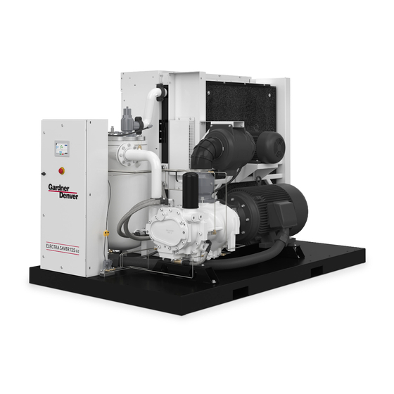
Operating and Service Manual
Genuine Gardner Denver Parts and Support Services
Information on genuine parts, support, and distributor contact.
Warning, Prohibition, and Label Information
Safety warnings, prohibitions, and label meanings.
Safety Precautions
General safety guidelines for operating the compressor.
Section 1: General Information
Compressor Description and Principle
Details the compressor's design and compression mechanism.
Air Flow in the System
Explains the path of air through the compressor system.
Lubrication, Cooling, and Sealing
Describes the role of oil in lubrication, cooling, and sealing.
Section 2: Installation
General Installation and Lifting
Instructions for unit receipt, lifting, and location selection.
Cold Weather Installation
Guidelines for installing and operating in cold weather conditions.
Piping and Electrical
Details on water piping, series/parallel, electrical wiring, and grounding.
Section 3: Starting & Operating Procedures
Prestart-Up Instructions
Steps to take before initial startup of the unit.
Starting and Stopping the Unit
Procedures for starting and stopping the compressor unit.
Controller Operations and Settings
Guide to controller login, parameter setting, and operation.
Section 4: Controls & Instrumentation
AirSmart™ G2 Controller Overview
Description of the controller's keypad and functions.
System Components and Diagrams
Explanation of valves, sensors, and schematic diagrams.
Capacity Control and Wiring
Details on capacity control, starters, and wiring diagrams.
Section 5: Lubrication, Oil Cooler, Oil Filter & Separator
Compressor Oil System and Lubricants
Oil system function, recommended lubricants, and specifications.
Moisture and Temperature Effects
Effects of moisture and high temperatures on oil and system.
Oil Filter and Separator Maintenance
Procedures for oil filter replacement and separator inspection.
Oil Cooler and Water Control
Information on oil coolers, water control valves, and system checks.
Section 6: Air Filter
Heavy-Duty Air Filter Service
Maintenance and cleaning of the heavy-duty air filter.
Filter Element Life and Inlet Tube
Criteria for filter element replacement and inlet tube inspection.
Section 7: Coupling
Coupling Assembly and Alignment
Steps for assembling, aligning, and servicing the compressor coupling.
Section 8: Maintenance Schedule
Service Check List
Routine maintenance checks at various intervals.
Section 9: Troubleshooting
Common Symptoms and Causes
Lists common issues like failure to start, stops, unload, and cycling.
Oil Consumption and Temperature Issues
Addresses oil carryover and high discharge temperature problems.
Standard Warranty
Warranty Period and Coverage
Details warranty periods and covered components.
Warranty Exclusions and Disclaimers
Lists conditions voiding warranty and legal disclaimers.
Table of Contents
Save PDF
Print
Rename the bookmark
Delete bookmark?
Delete from my manuals?
Login
Sign In
OR
Sign in with Facebook
Sign in with Google
Upload manual
Upload from disk
Upload from URL
Need help?
Do you have a question about the ST75-100G2A and is the answer not in the manual?
Questions and answers