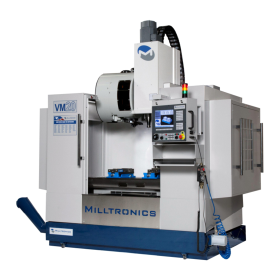
Summarization of Contents
Chapter 1 - Safety
Safety Checklist
List of essential checks for safe machine operation and maintenance.
Basic Safety Points
Fundamental safety guidelines for operating Milltronics machines.
Personal Safety and Attire
Guidelines on appropriate clothing and personal protective equipment for machine operation.
Workpiece and Tooling Safety
Safety considerations when machining workpieces and using tooling.
Machine Maintenance Safety
Safety precautions to be observed during machine maintenance procedures.
Electrical Safety Precautions
Critical safety rules related to electrical hazards and servicing.
Entrapment Prevention
Procedures and measures to prevent personnel from becoming trapped in the machine.
Machine Safety Labels Overview
Importance of understanding and adhering to safety and warning labels on the machine.
Safety Label Locations and Descriptions
Detailed guide to the location and meaning of safety and maintenance labels.
General Machine Safety Precautions
Essential safety precautions for operating milling and turning machines.
Pre-Operation Warmup and Daily Checks
Procedures for warming up and performing daily checks before operating the machine.
Spindle Operation Precautions
Safety guidelines and precautions for spindle operation to prevent damage.
Chapter 2 - Specification
Basic Machine Specifications
Key specifications including table load, weight, and tool changer details.
Coolant Recommendation
Advice on selecting non-toxic, non-corrosive coolants to protect machine paint.
Machine Layout Diagrams
Diagrams illustrating the physical layout and dimensions of VM series machines.
Machine Component Identification
Visual identification of key components on VM series machines with numbered diagrams.
Retention Knob Specifications
Chart detailing retention knob types, dimensions, and compatibility with different spindles.
Torque Specifications
Table of torque values for various machine components and fasteners.
Chapter 3 - Site Preparation
Machine Placement Guidelines
Guidelines for selecting an optimal location for the machine, considering slab, height, and environment.
Power and Ground Requirements
Essential requirements for electrical supply and grounding to ensure safe operation.
Chapter 4 - Installation
Transformer Connection Procedures
Guidelines for properly connecting transformers to the machine for power supply.
Autotransformer Wiring Diagram
Diagram illustrating input voltage selections and ground wire connections for autotransformers.
Air Supply System Setup
Connecting and adjusting the air supply system for optimal machine performance.
Machine Lifting Instructions
Safe procedures for lifting the machine using forklifts or cranes.
Installation Startup Checklist
Guidance for machine installation and checkout to activate the warranty.
Required Assembly Procedures
Instructions for installing and adjusting components removed for shipping.
Leveling and Tramming the Machine
Detailed steps for leveling and tramming the machine for precise operation.
Initial Machine Checks
Performing general, electrical checks, and verifying guards are in place.
Safety Checks and Testing
Procedures for testing emergency stop and enclosure safety circuits.
Spindle Start-up Procedure
Steps for running in and starting the spindle, including temperature monitoring.
Chapter 5 - Failure Modes, Detection and Prevention
Minimizing Wear and Tear
Tips for reducing wear and tear through good maintenance and installation practices.
Clearing Electrical Faults
Procedure for clearing faults in electrical components by cycling power.
Diagnosing Mechanical Faults
Methods for detecting and assessing mechanical failures using senses and inspection.
Chapter 6 - Maintenance
Periodic Maintenance and Safety Verification
Performing periodic maintenance and verifying safety systems are operational.
Maintenance Schedule
Routine maintenance tasks categorized by frequency: Always, Daily, Weekly, Monthly, Annually.
Air System Maintenance
Procedures for maintaining the air supply system, including regulator and lubricator adjustments.
Way Lube Maintenance
Ensuring proper lubrication of way systems, including reservoir levels and filter cleaning.
Automatic Tool Changer (ATC) Maintenance
Maintenance procedures for 24, 32, 40 pocket arm style and 16, 24 pocket carousel ATC.
Drawbar Cylinder Maintenance
Maintenance for inline spindle drawbar cylinders, focusing on fluid reservoir levels.
Chapter 7 – 8200 CNC Operation
8200 CNC Front Panel Overview
Identification and description of controls and indicators on the 8200 CNC front panel.
Power ON Procedure
Steps for turning on the main power switch and activating the CNC system.
Power OFF Procedure
Steps for safely turning off the machine, including engaging the E-Stop button.
Manual Pulse Generator (Handwheel) Operation
Using the handwheel for axis feed control in HDW mode.
Machine Function Buttons
Description of dedicated buttons controlling machine functions like block skip, coolant, and air blast.
Spindle Control Buttons
Operation of buttons for starting the spindle clockwise, counter-clockwise, or stopping it.
Emergency Stop Button
Function of the emergency stop button to disable motion and enable axis drives.
Enable Button Function
How to enable axis and spindle drives after releasing emergency stops and limit switches.


Need help?
Do you have a question about the VM15 and is the answer not in the manual?
Questions and answers