Table of Contents
Advertisement
Advertisement
Table of Contents

Related Manuals for Siemens SIMATIC BA 2xRJ45


Summarization of Contents
Legal Information
Warning notice system
Explains safety alert symbols and their meanings.
Qualified Personnel
Defines qualifications for operating the product/system.
Proper use of Siemens products
Notes on correct application and handling of Siemens products.
Trademarks
Lists registered and used trademarks.
Disclaimer of Liability
States the scope and limitations of liability.
Preface
Purpose of the documentation
Explains the manual's role and supplementation of other manuals.
Changes compared to previous version
Lists modifications from the prior manual version.
Conventions
Defines terms like "CPU" and "STEP 7" used in the manual.
Recycling and disposal
Provides guidance on environmentally friendly disposal of old equipment.
Security information
Information on industrial security functions and measures.
Siemens Industry Online Support
Details on accessing product support, examples, services, and forums.
Industry Mall
Describes the Siemens catalog and order system for automation products.
Guide
General information
Points to function manuals on general topics and communication.
Device information
Refers to manuals with detailed information on the BusAdapter.
Basic information
Indicates information on the BusAdapter and TIA Portal online help.
"mySupport"
Explains the personal work area for Industry Online Support functions.
"mySupport" - CAx data
Accessing product data like images, drawings, and manuals via mySupport.
Application examples
Provides tools and examples for solving automation tasks.
SIMATIC Automation Tool
Tool for commissioning and maintenance of SIMATIC S7 stations.
PRONETA
Network analysis tool for PROFINET during commissioning.
Product overview
Introduction
Explains how BusAdapters connect PROFINET IO to the ET 200SP system.
Supported PROFINET devices
Lists devices compatible with the BusAdapter, e.g., ET 200SP interface modules.
Overview
Presents a table of available SIMATIC BusAdapter versions.
BusAdapter BA 2xRJ45
4.1 Product overview
Details the article number, view, and properties of the BA 2xRJ45.
Properties
Explains connecting PROFINET IO and looping through PROFINET.
4.2 Connecting
Instructions for installing the bus connector.
Tools required
Lists necessary tools for connection.
Accessories required
Lists required accessories for connection.
Pin assignment
Details the signal names and pin assignments for the BA 2xRJ45.
Procedure
Step-by-step guide to connecting the BusAdapter BA 2xRJ45.
BusAdapter BA 2xRJ45 installed
Illustrates the installed BA 2xRJ45 with an ET 200SP CPU.
Note: Installation guidelines for modules with PROFINET IO interfaces
Provides important safety and connection guidelines for PROFINET IO modules.
4.3 Diagnostics
Shows LEDs and their meanings for diagnostics.
LEDs
Identifies the LEDs on the BusAdapter BA 2xRJ45.
LK1/LK2 LEDs on the BusAdapter
Explains the status and error displays of LK1/LK2 LEDs.
4.4 Technical specifications
Lists technical data like article number, interfaces, and ambient conditions.
BusAdapter BA 2xFC
5.1 Product overview
Details article number, view, and properties of the BA 2xFC.
Properties
Explains connecting PROFINET IO with FastConnect and looping through PROFINET.
5.2 Connecting
Instructions for installing the bus connector.
Tools required
Lists necessary tools for connection.
Accessories required
Lists recommended accessories for connection.
Pin assignment
Details signal names and pin assignments for the BA 2xFC.
Procedure
Step-by-step guide for connecting the PROFINET cable.
BusAdapter BA 2xFC installed
Illustrates the installed BA 2xFC with an ET 200SP CPU.
Note: Installation guidelines for modules with PROFINET IO interfaces
Provides important safety and connection guidelines for PROFINET IO modules.
5.3 Diagnostics
Shows LEDs and their meanings for diagnostics.
LEDs
Identifies the LEDs on the BusAdapter BA 2xFC.
LK1/LK2 LEDs on the BusAdapter
Explains status and error displays of LK1/LK2 LEDs.
5.4 Technical specifications
Lists technical data like article number, interfaces, and ambient conditions.
BusAdapter BA 2xSCRJ
6.1 Product overview
Details article number, view, and properties of the BA 2xSCRJ.
Properties
Explains connecting PROFINET IO optically with fiber-optic cables.
6.2 Connecting
Instructions for installing the bus connector.
Tools required
Lists necessary tools for connection.
Accessories required
Lists required fiber-optic cables and connectors.
Requirements
Explains preparation and installation of fiber-optic cables and connectors.
Pin assignment
Details signal names and pin assignments for the BA 2xSCRJ.
Procedure
Step-by-step guide for connecting the BusAdapter BA 2xSCRJ.
CAUTION: Risk of damage to eyes
Warns about potential eye damage from optical transmitter diodes.
BusAdapter BA 2xSCRJ installed
Illustrates the installed BA 2xSCRJ with an ET 200SP interface module.
Reusing used fiber-optic cables
Note on shortening fiber-optic cores to prevent attenuation losses.
Reference
Points to the SIMATIC NET PROFIBUS Network Manual for fiber-optic cables.
6.3 Diagnostics
Shows LEDs and their meanings for diagnostics.
LEDs
Identifies the LEDs on the BusAdapter BA 2xSCRJ.
LK1/LK2 and MT1/MT2 LEDs on the BusAdapter
Explains the status and error displays of LEDs.
6.4 Technical specifications
Lists technical data like article number, interfaces, and ambient conditions.
BusAdapter BA 2xLC
7.1 Product overview
Details article number, view, and properties of the BA 2xLC.
Properties
Explains connecting PROFINET IO with fiber-optic cables and looping through PROFINET.
7.2 Connecting
Instructions for installing the bus connector.
Tools required
Lists necessary tools for connection.
Accessories required
Lists required fiber-optic cables and connectors.
CAUTION: Cleaving the glass fiber
Warns about safe practices when cleaving glass fiber.
Pin assignment
Details signal names and pin assignments for the BA 2xLC.
Requirements
Explains preparation, bending radius, and lengths for fiber-optic cables.
Procedure
Step-by-step guide for connecting the BusAdapter BA 2xLC.
CAUTION: Risk of damage to eyes
Warns about potential eye damage from optical transmitter diodes.
BusAdapter BA 2xLC installed
Illustrates the installed BA 2xLC with an interface module.
Reusing used fiber-optic cables
Note on shortening fiber-optic cores to prevent attenuation losses.
Reference
Points to the SIMATIC NET PROFIBUS Network Manual for fiber-optic cables.
7.3 Diagnostics
Shows LEDs and their meanings for diagnostics.
LEDs
Identifies the LEDs on the BusAdapter BA 2xLC.
LK1/LK2 LEDs on the BusAdapter
Explains the status and error displays of LK1/LK2 LEDs.
7.4 Technical specifications
Lists technical data like article number, interfaces, and ambient conditions.
BusAdapter BA 2xM12
8.1 Product overview
Details article number, view, and properties of the BA 2xM12.
Properties
Lists features like M12 sockets, connection options, and immunity.
8.2 Connecting
Instructions for installing the bus connector.
Note: Push-pull connector
Recommendation for using push-pull connectors for simplified installation.
Tools required
Lists necessary tools for connection.
Accessories required
Lists required push-pull and M12 connecting cables.
Siemens pre-assembled connector/cable M12 D-coded without push/pull up to a maximum length of 15 m
Lists available pre-assembled M12 cables.
Siemens pre-assembled connector/cable M12 D-coded without push/pull up to a maximum length of 100 m
Information on custom M12 cable solutions.
Pin assignment
Details signal names and pin assignments for the BA 2xM12.
Procedure for standard M12 connector
Steps for connecting using standard M12 connectors.
Procedure for push-pull connectors
Steps for connecting using push-pull connectors.
Note: Simple unlocking of the push-pull connector without previous disassembly of the BusAdapter
Explains simple unlocking of push-pull connectors.
BusAdapter BA 2xM12 installed
Illustrates the installed BA 2xM12 with an interface module.
Note: Installation guidelines for modules with PROFINET IO interfaces
Provides important safety and connection guidelines for PROFINET IO modules.
Using accessories
Guidance on using strain relief and unlatching straps.
Compatibility of the M12 sockets used
Explains compatibility with different M12 connector types.
8.3 Diagnostics
Shows LEDs and their meanings for diagnostics.
LED displays
Identifies the LEDs on the BusAdapter BA 2xM12.
LK1/LK2 LEDs on the BusAdapter
Explains the status and error displays of LK1/LK2 LEDs.
8.4 Technical specifications
Lists technical data like article number, interfaces, and ambient conditions.
BusAdapter BA SCRJ/RJ45
9.1 Product overview
Details article number, view, and properties of the BA SCRJ/RJ45.
Properties
Explains connecting PROFINET IO via SCRJ and RJ45 ports.
9.2 Connecting
Instructions for installing the bus connector.
Connecting the SCRJ connector
Refers to connecting BusAdapter BA 2xSCRJ section.
Connecting the RJ45 connector
Refers to connecting BusAdapter BA 2xRJ45 section.
Pin assignment
Details signal names and pin assignments for the BA SCRJ/RJ45.
BA SCRJ/RJ45 BusAdapter mounted
Illustrates the mounted BA SCRJ/RJ45 with an interface module.
Note: Installation guidelines for modules with PROFINET IO interfaces
Provides important safety and connection guidelines for PROFINET IO modules.
9.3 Diagnostics
Shows LEDs and their meanings for diagnostics.
LEDs
Identifies the LEDs on the BusAdapter BA SCRJ/RJ45.
LK1/LK2 and MT LEDs on the BusAdapter
Explains the status and error displays of LEDs.
9.4 Technical specifications
Lists technical data like article number, interfaces, and ambient conditions.
BusAdapter BA SCRJ/FC
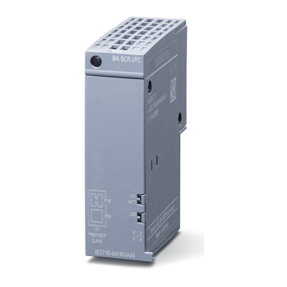
10.1 Product overview
Details article number, view, and properties of the BA SCRJ/FC.
Properties
Explains connecting PROFINET IO via SCRJ and FastConnect ports.
10.2 Connecting
Instructions for installing the bus connector.
Connecting the SCRJ connector
Refers to connecting BusAdapter BA 2xSCRJ section.
Connecting FC plug-in connectors
Refers to connecting BusAdapter BA 2xFC section.
Pin assignment
Details signal names and pin assignments for the BA SCRJ/FC.
Procedure
Step-by-step guide for connecting the BusAdapter BA SCRJ/FC.
BusAdapter BA SCRJ/FC installed
Illustrates the installed BA SCRJ/FC with an interface module.
Note: Installation guidelines for modules with PROFINET IO interfaces
Provides important safety and connection guidelines for PROFINET IO modules.
10.3 Diagnostics
Shows LEDs and their meanings for diagnostics.
LEDs
Identifies the LEDs on the BusAdapter BA SCRJ/FC.
LK1/LK2 and MT LEDs on the BusAdapter
Explains the status and error displays of LEDs.
10.4 Technical specifications
Lists technical data like article number, interfaces, and ambient conditions.
BusAdapter BA LC/RJ45
11.1 Product overview
Details article number, view, and properties of the BA LC/RJ45.
Properties
Explains connecting PROFINET IO via LC fiber-optic and RJ45 ports.
11.2 Connecting
Instructions for installing the bus connector.
Attaching LC connectors
Refers to connecting BusAdapter BA 2xLC section.
Connecting the RJ45 connector
Refers to connecting BusAdapter BA 2xRJ45 section.
Pin assignment
Details signal names and pin assignments for the BA LC/RJ45.
BusAdapter BA LC/RJ45 installed
Illustrates the installed BA LC/RJ45 with an interface module.
Note: Installation guidelines for modules with PROFINET IO interfaces
Provides important safety and connection guidelines for PROFINET IO modules.
11.3 Diagnostics
Shows LEDs and their meanings for diagnostics.
LEDs
Identifies the LEDs on the BusAdapter BA LC/RJ45.
LK1/LK2 LEDs on the BusAdapter
Explains the status and error displays of LK1/LK2 LEDs.
11.4 Technical specifications
Lists technical data like article number, interfaces, and ambient conditions.
BusAdapter BA LC/FC
12.1 Product overview
Details article number, view, and properties of the BA LC/FC.
Properties
Explains connecting PROFINET IO via LC fiber-optic and FastConnect ports.
12.2 Connecting
Instructions for installing the bus connector.
Attaching LC connectors
Refers to connecting BusAdapter BA 2xLC section.
Connecting FastConnect bus cable
Refers to connecting BusAdapter BA 2xFC section.
Pin assignment
Details signal names and pin assignments for the BA LC/FC.
BusAdapter BA LC/FC installed
Illustrates the installed BA LC/FC with an interface module.
Note: Installation guidelines for modules with PROFINET IO interfaces
Provides important safety and connection guidelines for PROFINET IO modules.
12.3 Diagnostics
Shows LEDs and their meanings for diagnostics.
LEDs
Identifies the LEDs on the BusAdapter BA LC/FC.
LK1/LK2 LEDs on the BusAdapter
Explains the status and error displays of LK1/LK2 LEDs.
12.4 Technical specifications
Lists technical data like article number, interfaces, and ambient conditions.
Strain relief
13.1 Product overview
Details article number, view, and properties of the strain relief.
Properties
Explains the strain relief as a protective device for PROFINET cables.
13.2 Installing
Instructions for installing the strain relief.
Requirement
States conditions for mounting the strain relief.
Tools required
Lists necessary tools for installation.
Procedure
Step-by-step guide for installing the strain relief.
Strain relief installed
Illustrates the installed strain relief with a BusAdapter.
Dimension drawings
A.1 BusAdapter dimension drawings
Shows dimensional drawings for the BusAdapter BA 2xRJ45 as an example.
A.2 Strain relief dimension drawings
Shows the dimensional drawing of the strain relief.
Accessories
B.1 Accessories
Lists additional accessories like strain relief and labels.
Cables and connectors
Mentions recommended cables and connectors.
Assembly tools
Lists tools for cable preparation.
Compatibility
Overview of the introduction of the BusAdapter in the engineering tools
Table showing compatibility with STEP 7 and TIA Portal versions.
Need help?
Do you have a question about the SIMATIC BA 2xRJ45 and is the answer not in the manual?
Questions and answers