
Related Manuals for Rockford Fosgate TM500X1br


Summarization of Contents
Introduction
Practice Safe Sound
Continuous exposure to sound pressure levels over 100dB may cause permanent hearing loss.
Safety
This symbol with “WARNING” is intended to alert the user to the presence of important instructions.
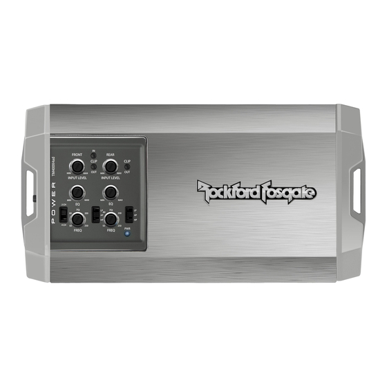
Design Features
Input Clip Indicator
The input clip indicator works in conjunction with the audio source volume knob, illuminating red when audio source reaches it's clipping point.
Input Level Knob
The input level control is used to match the output of the audio source.
Punch EQ
A Gyrator based Punch EQ that eliminates frequency shift with boost. This works along with the crossover switch.
Power/Protect LED
Power LED illuminates blue when the unit is turned on. Protect LED illuminates yellow if a short circuit or low impedance is detected.
Installation
Installation Considerations
This section focuses on some of the vehicle considerations for installing your new amplifier. Pre-planning your system layout and best wiring routes will save installation time.
Mounting Locations
To ensure optimal performance, mount the amplifier with at least 1" (2.54cm) of air gap around the amplifier's heat sink to provide proper cooling.
Battery and Charging
Amplifiers will put an increased load on the vehicle's battery and charging system. We recommend checking your alternator and battery condition.
Wiring the System
This section details the steps for connecting the amplifier's power, ground, and signal wires to the vehicle's electrical system and source unit.
Operation
Input Clip Indicator Setup
Step-by-step guide on how to set the input clip indicator to properly adjust source unit volume and input level.
Output Clip Indicator Setup
Guide on adjusting the Input Level knob until the Output Clip Indicator illuminates to the appropriate color.
Adjusting Crossover Frequency
Instructions for setting the crossover switch (HP, AP, LP) and adjusting the crossover frequency knob for each channel.
2/4 Channel Switch
Explanation of how the 2CH and 4CH switch settings affect input modes for 4-channel amplifiers.
Punch EQ
Explanation of the Punch EQ feature, how it works with crossover settings, and how to adjust it.
Troubleshooting
Check Amplifier for proper connections
Verify that the POWER light is on and check fuses, ground connection, and voltage at battery and remote turn-on.
Protect light is on
Check for short circuits in speaker connections or low speaker impedance causing the Protect light to illuminate.
Check Amplifier for audio output
Verify RCA input connections, test entire cable length, and test amplifier input with a known good source.
Check Amplifier if you experience Turn-on Pop
Disconnect input signal, turn amplifier on/off, and consider a delay turn-on module or different 12 Volt source.
Check Amplifier if you experience excess Engine Noise
Route signal wires away from power/ground wires, bypass components, reground components, or test vehicle electrical system.
Remote not functioning
Verify amplifier remote switch is in “ON” position or remote is plugged into the remote PLC “IN” port.
Need help?
Do you have a question about the TM500X1br and is the answer not in the manual?
Questions and answers