Rockford Fosgate T400X2ad Installation & Operation Manual
Hide thumbs
Also See for T400X2ad:
- Installation & operation manual (10 pages) ,
- Operation manual (10 pages)
Advertisement
Table of Contents
- 1 Table of Contents
- 2 Introduction
- 3 Specifications
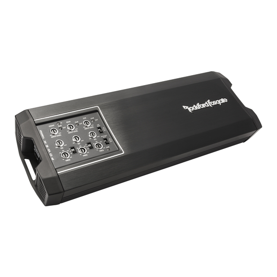
- 4 Design Features
- 5 Installation
- 6 Installation Considerations
- 7 Mounting Locations
- 8 Battery and Charging
- 9 Wiring the System
- 10 Operation
- 11 Adjusting Crossover Frequency
- 12 2/4 Channel Switch
- 13 Punch EQ
- 14 Troubleshooting
- Download this manual
See also:
Operating Manual
Advertisement
Table of Contents


Need help?
Do you have a question about the T400X2ad and is the answer not in the manual?
Questions and answers