Sign In
Upload
Download
Table of Contents
Contents
Add to my manuals
Delete from my manuals
Share
URL of this page:
HTML Link:
Bookmark this page
Add
Manual will be automatically added to "My Manuals"
Print this page
×
Bookmark added
×
Added to my manuals
Manuals
Brands
Topcon Manuals
Measuring Instruments
GPT-3007
Instruction manual
Topcon GPT-3007 Instruction Manual
Pulse total station
Hide thumbs
1
2
3
4
5
6
7
Table Of Contents
8
9
10
11
12
13
14
15
16
17
18
19
20
21
22
23
24
25
26
27
28
29
30
31
32
33
34
35
36
37
38
39
40
41
42
43
44
45
46
47
48
49
50
51
52
53
54
55
56
57
58
59
60
61
62
63
64
65
66
67
68
69
70
71
72
73
74
75
76
77
78
79
80
81
82
83
84
85
86
87
88
89
90
91
92
93
94
95
96
97
98
99
100
101
102
103
104
105
106
107
108
109
110
111
112
113
114
115
116
117
118
119
120
121
122
123
124
125
126
127
128
129
130
131
132
133
134
135
136
137
138
139
140
141
142
143
144
145
146
147
148
149
150
151
152
153
154
155
156
157
158
159
160
161
162
163
164
165
166
167
168
169
170
171
172
173
174
175
176
177
178
179
180
page
of
180
Go
/
180
Contents
Table of Contents
Bookmarks
Table of Contents
General Handling Precautions
Display for Safe Use
Safety Cautions
User
Exceptions from Responsibility
Laser Safety
Labels
Symbol Mark While the Laser Is Emitting
Table of Contents
Standard Set Composition
1 Nomenclature and Functions
Nomenclature
Display
Operating Key
Function Key (Soft Key)
Star Key Mode
Serial Signal RS-232C Connector
2 Preparation for Measurement
Power Connection
Setting Instrument up for Measurement
Power Switch Key on
Battery Power Remaining Display
Vertical and Horizontal Angle Tilt Correction
How to Enter Alphanumeric Characters
Point Guide
Laser Plummet ON/OFF (Only for Laser Plummet Type)
3 Angle Measurement
Measuring Horizontal Angle Right and Vertical Angle
Switching Horizontal Angle Right/Left
Measuring from the Required Horizontal Angle
Setting by Holding the Angle
Setting a Horizontal Angle from the Keys
Vertical Angle Percent Grade(%) Mode
Repetition Angle Measurement
Buzzer Sounding for Horizontal Angle 90° Increments
Compasses ( Vertical Angle)
4 Distance Measurement
Setting of the Atmospheric Correction
Setting of the Correction for Prism Constant / Non-Prism Constant
Distance Measurement (Continuous Measurement)
Distance Measurement (N-Time Measurement/Single Measurement)
Fine Mode/Tracking Mode/Coarse Mode
Stake out (S.O)
Offset Measurement
Angle Offset
Distance Offset Measurement
Plane Offset Measurement
Column Offset Measurement
5 Coordinate Measurement
Setting Coordinate Values of Occupied Point
Setting Height of the Instrument
Setting Height of Target (Prism Height)
Execution of Coordinate Measuring
6 SPECIAL MODE (Menu Mode)
Application Measurement (PROGRAMS)
Remote Elevation Measurement (REM)
Missing Line Measurement (MLM)
Setting Z Coordinate of Occupied Point
Area Calculation
Point to Line Measurement
Setting the GRID FACTOR
Setting Illumination of Display and Cross Hairs
Setting Mode 1
Setting Minimum Reading
Auto Power off
Vertical and Horizontal Angle Tilt Correction ( Tilt ON/OFF)
Systematic Error of Instrument Correction (Only for GPT-3002/3003/3005)
Selecting Battery Type
Heater ON/OFF
Setting RS-232C Communication with External Device
Setting Contrast of Display
7 Data Collection
Preparation
Selecting a File for Data Collection
Selecting a Coordinate File for Data Collection
Occupied Point and Backsight Point
Operational Procedure of DATA COLLECT
Searching the Recorded Data
Entering PCODE / ID Using PCODE Library
Entering PCODE / ID from the List of PCODE
Data Collect Offset Measurement Mode
Angle Offset Measurement
Distance Offset Measurement
Plane Offset Measurement
Column Offset Measurement
NEZ Auto Calculation
Point to Line Measurement
To Change to the Point to Line Measurement
Executing a Point to Line Measurement
Editing PCODE Library [PCODE INPUT]
Setting Parameter of Data Collect [CONFIG.]
8 Layout
Preparation
Setting the GRID FACTOR
Selecting Coordinate Data File
Setting Occupied Point
Setting Backsight Point
Executing a Layout
Layout of Coordinates of Point to Line
Setting a New Point
Side Shot Method
Resection Method
9 Memory Manager Mode
Display Internal Memory Status
Searching Data
Measured Data Searching
Coordinate Data Searching
PCODE LIBRARY Searching
File Maintenance
Rename a File
Searching Data in a File
Deleting a File
Coordinate Data Direct Key Input
Coordinate Data Input
PTL (Point to Line) Data Input
Delete a Coordinate Data from a File
Editing PCODE Library
Data Communications
Sending Data
Loading Data
Setting Parameter of Data Communications
Initialization
10 Set Audio Mode
11 Setting the Prism / Non-Prism Constant Value
12 Setting Atmospheric Correction
Calculation of Atmospheric Correction
Setting of Atmospheric Correction Value
13 Correction for Refraction and Earth Curvature
Distance Calculation Formula
14 Power Source and Charging
On-Board Battery BT-52QA
15 Detach/Attach of Tribrach
16 Selecting Mode
Items of the Selecting Mode
How to Set Selecting Mode
17 Check and Adjustment
Checking and Adjusting of Instrument Constant
Checking the Optical Axis
Checking the Optical Axis of EDM and Theodolite
Checking the Optical Axis of Laser Pointer
Checking/Adjusting the Theodolite Functions
Checking /Adjusting the Plate Level
Checking /Adjusting the Circular Level
Adjustment of the Vertical Cross-Hair
Collimation of the Instrument
Checking / Adjusting the Optical Plummet Telescope
Checking / Adjusting the Laser Plummet (for Laser Plummet Type)
Adjustment of Vertical Angle 0 Datum
How to Set the Instrument Constant Value
Adjustment of Compensation Systematic Error of Instrument
EDM Alignment Checking Mode
18 Precautions
19 Special Accessories
20 Battery System
21 Prism System
22 Error Displays
23 Specifications
Appendix
Dual Axis Compensation
Precaution When Charging or Storing Batteries
Advertisement
Quick Links
Download this manual
INSTRUCTION MANUAL
PULSE TOTAL STATION
GPT-3000
SERIES
GPT-3002
GPT-3003
GPT-3005
GPT-3007
Table of
Contents
Previous
Page
Next
Page
1
2
3
4
5
Advertisement
Table of Contents
Need help?
Do you have a question about the GPT-3007 and is the answer not in the manual?
Ask a question
Questions and answers
Related Manuals for Topcon GPT-3007
Measuring Instruments Topcon GPT-8001A Instruction Manual
Automatic tracking pulse total station; servo pulse total station (145 pages)
Measuring Instruments Topcon GPT-3002W Series Instruction Manual
Pulse total stations (188 pages)
Measuring Instruments Topcon Series GPT-3005W Series Instruction Manual
Pulse total stations (188 pages)
Measuring Instruments Topcon GPT-3000 Series Instruction Manual
Pulse total station (180 pages)
Measuring Instruments Topcon GPT-3005 Instruction Manual
Pulse total station (180 pages)
Measuring Instruments Topcon GPT-7500 Series Instruction Manual
Electronic total station (134 pages)
Measuring Instruments Topcon GTS-750 Series Instruction Manual
Electronic total station (134 pages)
Measuring Instruments Topcon GPT-7000i Series Instruction Manual
Imaging total station (116 pages)
Measuring Instruments Topcon GTS-230N Instruction Manual
Electronic total station gts-230n series (184 pages)
Measuring Instruments Topcon Synergy GM-50 series Instruction Manual
Geodetic measurement station (220 pages)
Measuring Instruments Topcon GM-100 Series Instruction Maunal
Geodetic measurement station (229 pages)
Measuring Instruments Topcon GTS-230W Series Instruction Manual
Electronic total station (167 pages)
Measuring Instruments Topcon GTS-600 Series Instruction Manual
(144 pages)
Measuring Instruments Topcon GTS-230 Series Instruction Manual
Electronic total station (163 pages)
Measuring Instruments Topcon GREEN LABEL GTS-250 Series Instruction Manual
Electronic total station (176 pages)
Measuring Instruments Topcon GREEN LABEL GTS-255 Instruction Manual
Electronic total station (176 pages)
Summarization of Contents
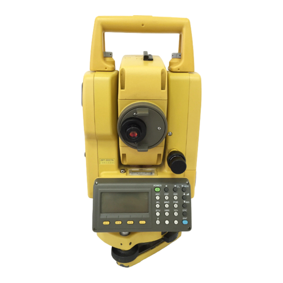
NOMENCLATURE AND FUNCTIONS
1.1 Nomenclature
Identifies and labels the main parts of the instrument.
1.2 Display
Explains the instrument's display screen and its marks.
1.3 Operating Key
Details the function of each key on the instrument's control panel.
1.4 Function Key (Soft Key)
Describes the functions assigned to the soft keys in different modes.
1.5 Star key mode
Explains how to access and use the instrument's option menu via the star key.
1.6 Serial signal RS-232C connector
Describes the serial port for computer communication and data transfer.
PREPARATION FOR MEASUREMENT
2.1 Power Connection
Guides on connecting the instrument's power source, including battery options.
2.2 Setting Instrument Up For Measurement
Step-by-step instructions for leveling and centering the instrument on a tripod.
2.3 Power Switch Key ON
Details the procedure for turning on the instrument and initial checks.
2.4 Battery Power Remaining Display
Explains how to interpret the battery level indicator and its implications.
2.5 Vertical and Horizontal Angle Tilt Correction
Describes the automatic tilt correction feature for accurate angle measurements.
2.6 How to Enter Alphanumeric characters
Explains the method for inputting text and numbers using the instrument's interface.
2.7 Point Guide
Describes the Point Guide feature for assisting stake-out work.
2.8 Laser Plummet ON/OFF
Explains how to turn the laser plummet on and off for centering the instrument.
ANGLE MEASUREMENT
3.1 Measuring Horizontal Angle Right and Vertical Angle
Details the procedure for measuring horizontal and vertical angles.
3.2 Switching Horizontal Angle Right/Left
Explains how to switch between right and left horizontal angle measurement modes.
3.3 Measuring from the Required Horizontal Angle
Covers setting and holding specific horizontal angles for measurements.
3.4 Vertical Angle Percent Grade(%) Mode
Describes how to measure vertical angles in percent grade mode.
3.5 Repetition Angle Measurement
Explains the process for performing repetitive angle measurements for increased accuracy.
3.6 Buzzer Sounding for Horizontal Angle 90° Increments
Details the buzzer function for audible feedback at 90° horizontal angle increments.
3.7 Compasses ( vertical angle)
Explains how the vertical angle is displayed and potentially used in compass mode.
DISTANCE MEASUREMENT
4.1 Setting of the Atmospheric Correction
Guides on setting atmospheric correction values for accurate distance measurements.
4.2 Setting of the Correction for Prism Constant / Non-prism Constant
Explains how to set correction values for prisms and non-prism targets.
4.3 Distance Measurement (Continuous Measurement)
Describes how to perform continuous distance measurements.
4.4 Distance Measurement (N-time Measurement/Single Measurement)
Explains N-time and single distance measurement procedures.
4.5 Fine Mode/Tracking Mode/Coarse Mode
Details the different distance measurement modes and their characteristics.
4.6 Stake Out (S.O)
Explains the Stake Out function for marking points in the field.
4.7 Offset Measurement
Covers various offset measurement modes for inaccessible points, including Angle, Distance, Plane, and Column offsets.
COORDINATE MEASUREMENT
5.1 Setting Coordinate Values of Occupied Point
Guides on inputting the instrument's location coordinates.
5.2 Setting Height of the Instrument
Explains how to input the height of the instrument for calculations.
5.3 Setting Height of Target (Prism Height)
Details how to input the height of the prism or target.
5.4 Execution of Coordinate Measuring
Describes the process of performing coordinate measurements after setup.
SPECIAL MODE (Menu Mode)
6.1 Application Measurement (PROGRAMS)
Introduces special measurement programs available in the instrument, such as REM, MLM, Z Coord, Area, Point to Line.
6.2 Setting the GRID FACTOR
Explains how to set and use the grid factor for coordinate transformations.
6.3 Setting Illumination of Display and Cross Hairs
Guides on adjusting display brightness and reticle illumination.
6.4 Setting Mode 1
Covers various instrument settings like minimum reading, auto power off, tilt correction, and communication.
6.5 Setting Contrast of Display
Explains how to adjust the display contrast for better readability.
DATA COLLECTION
7.1 Preparation
Covers initial steps for data collection, including file selection and setting points.
7.2 Operational Procedure of DATA COLLECT
Provides the main workflow for collecting data using the instrument.
7.3 Data Collect Offset Measurement mode
Covers specialized offset measurement techniques within data collection.
7.4 NEZ Auto Calculation
Guides on automatic calculation and storage of North, East, Zenith coordinates.
7.5 Point to Line Measurement
Details measuring offset points relative to a defined line.
7.6 Editing PCODE LIBRARY [PCODE INPUT]
Covers managing and editing the PCODE library for data collection.
7.7 Setting Parameter of Data Collect [CONFIG.]
Allows configuring various parameters for the data collection process.
LAYOUT
8.1 Preparation
Covers initial setup and preparation for layout operations.
8.2 Executing a Layout
Provides the procedure for executing layout operations to stake out points.
8.3 Setting a New Point
Covers methods for establishing new points during layout.
MEMORY MANAGER MODE
9.1 Display Internal Memory Status
Shows how to check the status and capacity of the instrument's internal memory.
9.2 Searching Data
Explains methods for searching recorded data files.
9.3 FILE MAINTENANCE
Covers file management operations like renaming, searching, and deleting.
9.4 Coordinate Data Direct Key Input
Explains how to input coordinate data directly via the keyboard.
9.5 Delete a Coordinate Data from a File
Guides on deleting specific coordinate data entries from a file.
9.6 Editing PCODE Library
Covers adding, editing, or deleting entries in the PCODE library.
9.7 Data Communications
Explains how to transfer data between the instrument and a computer.
9.8 Initialization
Describes how to reset the instrument's internal memory to its default state.
SET AUDIO MODE
SETTING THE PRISM / NON-PRISM CONSTANT VALUE
SETTING ATMOSPHERIC CORRECTION
12.1 Calculation of Atmospheric Correction
Explains the formulas and factors used for atmospheric correction.
12.2 Setting of Atmospheric Correction Value
Guides on inputting temperature and pressure for atmospheric correction.
CORRECTION FOR REFRACTION AND EARTH CURVATURE
13.1 Distance Calculation Formula
Provides the formulas used for calculating distances with corrections.
POWER SOURCE AND CHARGING
14.1 On-board Battery BT-52QA
Details the procedure for removing, charging, and installing the on-board battery.
DETACH/ATTACH OF TRIBRACH
SELECTING MODE
16.1 Items of the Selecting Mode
Lists the various selectable modes and their functions.
16.2 How to Set Selecting Mode
Provides instructions on how to configure instrument settings through the selecting mode.
CHECK AND ADJUSTMENT
17.1 Checking and adjusting of instrument constant
Guides on verifying and adjusting the instrument's constant values.
17.2 Checking the Optical Axis
Explains procedures to check the alignment of EDM, theodolite, and laser pointer optics.
17.3 Checking/Adjusting the Theodolite Functions
Covers checking and adjusting various theodolite functions for precision.
17.4 How to Set the Instrument Constant Value
Guides on setting the instrument's constant values for prism and non-prism modes.
17.5 Adjustment of Compensation Systematic Error of Instrument
Details the adjustment procedure for systematic instrument errors.
17.6 EDM Alignment Checking mode
Explains how to check and align the EDM axis with the optical axis.
PRECAUTIONS
SPECIAL ACCESSORIES
SPECIFICATIONS
APPENDIX
1 Dual Axis Compensation
Explains the concept and impact of dual axis compensation on angle measurements.
APPENDIX
2 Precaution when Charging or Storing Batteries
Provides guidelines for proper battery charging, usage, and storage.
Table of Contents
Save PDF
Print
Rename the bookmark
Delete bookmark?
Delete from my manuals?
Login
Sign In
OR
Sign in with Facebook
Sign in with Google
Upload manual
Upload from disk
Upload from URL
Need help?
Do you have a question about the GPT-3007 and is the answer not in the manual?
Questions and answers