Table of Contents
Advertisement
Quick Links
BLUE-FLAME VENT-FREE
PROPANE GAS HEATER
OWNER'S OPERATION AND INSTALLATION MANUAL
WARNING: If the information in this manual is not followed exactly, a fire or
explosion may result causing property damage, personal injury, or loss of life.
— Do not store or use gasoline or other flammable vapors and liquids in the
vicinity of this or any other appliance.
— WHAT TO DO IF YOU SMELL GAS
• Do not try to light any appliance.
• Do not touch any electrical switch; do not use any phone in your building.
• Immediately call your gas supplier from a neighbor's phone. Follow the
gas supplier's instructions.
• If you cannot reach your gas supplier, call the fire department.
— Installation and service must be performed by a qualified installer, service
agency, or the gas supplier.
Model: RP30B and CGP18B
Save this manual for future reference.
®
Advertisement
Table of Contents

Related Manuals for Desa CGP18B


Summary of Contents for Desa CGP18B
- Page 1 BLUE-FLAME VENT-FREE PROPANE GAS HEATER OWNER’S OPERATION AND INSTALLATION MANUAL Model: RP30B and CGP18B WARNING: If the information in this manual is not followed exactly, a fire or explosion may result causing property damage, personal injury, or loss of life.
-
Page 2: Table Of Contents
CONTENTS SAFETY INFORMATION SECTION Safety Information ... 2 Product Identification ... 4 Local Codes ... 4 Unpacking ... 4 Product Features ... 4 Fresh Air For Combustion And Ventilation ... 5 Installing To Wall ... 9 Connecting To Gas Supply ... 14 Checking Gas Connections ... - Page 3 SAFETY INFORMATION Continued 100098 WARNINGS WARNING ICON G 001 WARNING: Any change to this heater or its controls can be dangerous. 1. Use only propane gas. Do not convert heater to use different fuel type. 2. Do not place propane supply tank(s) inside any structure. Locate propane supply tank(s) outdoors.
-
Page 4: Product Identification
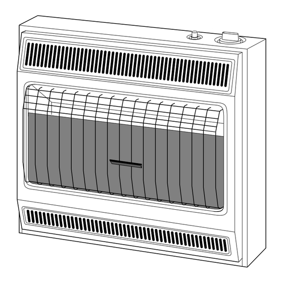
FEATURES Front Panel Figure 1 - Vent-Free Propane Gas Heater Install and use heater with care. Follow all local codes. In the absence of local codes, use the latest edition of National Fuel Gas Code ANSI Z223.1, also known as NFPA 54*. -
Page 5: Fresh Air For Combustion And Ventilation
FRESH AIR COMBUSTION VENTILATION 100098 WARNING ICON G 001 This heater must have fresh air for proper operation. If not, poor fuel combustion could result. Read the following instructions to insure proper fresh air for this and other fuel-burning appliances in your home. -
Page 6: Determining Fresh-Air Flow For Heater Location
2560 cu. ft. (volume of space) BTU/Hr the space can support) 3. Add the BTU/Hr of all fuel burning appliances in the space. Vent-free heater Gas water heater* Gas furnace Vented gas heater Gas fireplace logs Other gas appliances* Total Example: Gas water heater... -
Page 7: Ventilation Air
FRESH AIR COMBUSTION VENTILATION Continued 100098 VENTILATION AIR Ventilation Air From Inside Building This fresh air would come from an adjoining unconfined space. When ventilating to an adjoining unconfined space, you must provide two permanent openings: one within 12" of the ceiling and one within 12"... - Page 8 FRESH AIR COMBUSTION VENTILATION Continued VENTILATION AIR (Continued) Ventilation Air From Outdoors Provide extra fresh air by using ventilation grills or ducts. You must provide two perma- nent openings: one within 12" of the ceiling and one within 12" of the floor. Connect these items directly to the outdoors or spaces open to the outdoors.
-
Page 9: Installing To Wall
Maintain the minimum clearances shown in Figure 4 (page 10). If you can, provide greater clearances from floor, ceiling, and joining wall. You can locate model CGP18B on floor, away from a wall. An optional floor mounting stand is needed. Purchase the floor mounting stand from your dealer. See Accessories, page 27. - Page 10 CEILING 6" Minimum From Sides Of Heater Left Side FLOOR Figure 4 - Mounting Clearances As Viewed From Front of Heater CAUTION 36" Minimum Right Side Minimum To Floor " - RP30B *3" - CGP18B 100098...
- Page 11 2. Lift straight up on grill guard until it stops. Grill guard will slide up about 1/4". 3. Pull bottom of front panel forward, then down. 4. Remove cardboard packing from grill and glass (CGP18B) or heat shield (RP30B). FRONT PANEL REMOVAL G...
- Page 12 Figure 8 - Folding Anchor 3. Insert wall anchor (wings first) into hole. Tap anchor flush to wall. WARNING 7 1/4" 16" Min. Only Insert Mounting 32 1/2" Screws Through Last Min. Hole On Each End Floor CGP18B 18 3/4" Min. 100098...
- Page 13 INSTALLING TO WALL Continued 100098 4. For thin walls (1/2" or less), insert red key into wall anchor. Push red key to “pop” open anchor wings. IMPORTANT: For thick walls (over 1/2" thick) or solid walls, do not pop open wings. Figure 9 - Popping Open Anchor Wings For Thin Walls 5.
-
Page 14: Connecting To Gas Supply
CONNECTING TO GAS SUPPLY A qualified service person must connect heater to gas supply. Follow all local codes. WARNING ICON Never connect heater directly to the propane supply. This heater requires an external regulator (not supplied). Install the external regulator between the heater and propane supply. The installer must supply an external regulator. -
Page 15: Checking Gas Connections
CONNECTING TO GAS SUPPLY Continued CHECKING CONNECTIONS 100098 Hold pressure regulator with wrench when connecting it to gas piping IMPORTANT: and/or fittings. Pressure Regulator 1/2" NPT Pipe Nipple Tee Joint Test Reducer Bushing to Gauge 1/8" NPT Connection * 1/8" NPT Plug Tap Tee Joint Sediment... - Page 16 CHECKING CONNECTIONS Continued 3. Pressurize supply piping system by either using compressed air or opening propane supply tank valve. 4. Check all joints of gas supply piping system. Apply mixture of liquid soap and water to gas joints. Bubbles forming show a leak. 5.
-
Page 17: Operating Heater
OPERATING HEATER 100098 FOR YOUR SAFETY READ BEFORE LIGHTING WARNING ICON G 001 If you do not follow these instructions exactly, a fire or explosion may result causing property damage, personal injury or loss of life. A. This appliance has a pilot which must be lighted by hand. When lighting the pilot, follow these instructions exactly. - Page 18 OPERATING HEATER Continued 4. Wait five (5) minutes to clear out any gas. Then smell for gas, including near the floor. If you smell gas, STOP! Follow “B” in the safety information at the top of page 17. If you don’t smell gas, go to the next step. 5.
-
Page 19: To Turn Off Gas To Appliance
OPERATING HEATER Continued INSPECTING BURNER 100098 TO TURN OFF GAS TO APPLIANCE Shutting Off Heater 1. Turn control knob clockwise 2. Press in control knob and turn clockwise 3. Turn off all electric power to the appliance if service is to be performed. Shutting Off Burner Only (pilot stays lit) 1. -
Page 20: Burner Flame Pattern
INSPECTING BURNER Continued If pilot flame pattern is incorrect, as shown in Figure 19 • turn heater off (see To Turn Off Gas to Appliance, page 19) • see Troubleshooting, pages 21 through 24 BURNER FLAME PATTERN Figure 20 shows a correct burner flame pattern. Figure 21 shows an incorrect burner flame pattern. -
Page 21: Cleaning And Maintenance
CLEANING MAINTENANCE TROUBLE- SHOOTING Note: All troubleshooting items are listed in order of operation. 100098 WARNING ICON G 001 Turn off heater and let cool before cleaning. WARNING ICON G 001 You must keep control areas, burner, and circulating air passageways of heater clean. - Page 22 TROUBLE- SHOOTING Continued OBSERVED POSSIBLE PROBLEM CAUSE When ignitor button 1. Gas supply turned off is pressed, there is or manual shutoff spark at ODS/pilot valve closed but no ignition 2. Control knob not in PILOT position 3. Control knob not pressed in while in PILOT position 4.
- Page 23 TROUBLE- SHOOTING Continued 100098 OBSERVED POSSIBLE PROBLEM CAUSE Burner does not light 2. Burner orifice diameter after ODS/pilot is lit is too small (continued from 3. Inlet gas pressure is page 22) too low Delayed ignition of 1. Manifold pressure is burner too low 2.
- Page 24 TROUBLE- SHOOTING Continued WARNING ICON G 001 If you smell gas • Shut off gas supply. • Do not try to light any appliance. • Do not touch any electrical switch; do not use any phone in your building. • Immediately call your gas supplier from a neighbor’s phone.
-
Page 25: Technical Service
SERVICE SPECIFICATIONS SERVICE HINTS 100098 You may have further questions about installation, operation, or troubleshooting. If so, contact DESA International’s Technical Service Department at 1-800-323-5190. BTU (Variable) Type Gas Ignition Pressure Regulator Setting Inlet Gas Pressure (inches of water) Maximum... -
Page 26: Replacement Parts
Parts Under Warranty Contact authorized dealers of this product. If they can’t supply original replacement part(s), either contact your nearest Parts Central (see below) or call DESA International’s Technical Service Department at 1-800-323-5190. When calling, have ready •... -
Page 27: Accessories
Purchase these heater accessories from your local dealer. If they can not supply these accessories, either contact your nearest Parts Central (see page 26) or call DESA International’s Parts Department at 1-800-972-7879 for information.You can also write to the address listed on the back page of this manual to receive these accessories. -
Page 29: Parts List
RP30B PARTS LIST 10-1 10-2 100098 This list contains replaceable parts used in your heater. When ordering parts, follow the instructions listed under Replacement Parts on page 26 of this manual. PART NUMBER DESCRIPTION 098304-01 Screw, #10 x 3/8" 098345-01AC Front Panel 098197-04 Grill Guard... - Page 31 CGP18B PARTS LIST 12-1 12-2 100098 This list contains replaceable parts used in your heater. When ordering parts, follow the instructions listed under Replacement Parts on page 26 of this manual. PART NUMBER DESCRIPTION 098304-01 Screw, #10 x 3/8" 098742-03...
-
Page 32: Warranty Information
We make no other warranty, expressed or implied. DESA International warrants this product to be free from defects in materials and components for one (1) year from the date of first purchase, provided that the product has been properly installed, operated and maintained in accordance with all applicable instructions.
Need help?
Do you have a question about the CGP18B and is the answer not in the manual?
Questions and answers