Table of Contents
Advertisement
Quick Links
VENT-FREE PROPANE GAS HEATER
OWNER'S OPERATION AND INSTALLATION MANUAL
WARNING: If the information in this manual
is not followed exactly, a fire or explosion
may result causing property damage, per-
sonal injury, or loss of life.
— Do not store or use gasoline or other
flammable vapors and liquids in the
vicinity of this or any other appliance.
— WHAT TO DO IF YOU SMELL GAS
• Do not try to light any appliance.
• Do not touch any electrical switch; do
not use any phone in your building.
• Immediately call your gas supplier from
a neighbor's phone. Follow the gas
supplier's instructions.
• If you cannot reach your gas supplier,
call the fire department.
— Installation and service must be per-
formed by a qualified installer, service
agency, or the gas supplier.
Model: CGP11
Save this manual for future reference.
WARNING
: Improper installation,
adjustment, alteration, service, or
maintenance can cause injury or
property damage. Refer to this
manual for correct installation and
operational procedures. For assis-
tance or additional information
consult a qualified installer, ser-
vice agency, or the gas supplier.
A
G S
®
®
Advertisement
Table of Contents

Subscribe to Our Youtube Channel
Related Manuals for Desa Comfort Glow CGP11


Summary of Contents for Desa Comfort Glow CGP11
- Page 1 — Installation and service must be per- formed by a qualified installer, service agency, or the gas supplier. Save this manual for future reference. Model: CGP11 WARNING adjustment, alteration, service, or maintenance can cause injury or property damage. Refer to this manual for correct installation and operational procedures.
-
Page 2: Table Of Contents
CONTENTS SECTION Safety Information ... 2 Product Identification ... 4 Local Codes ... 4 Unpacking ... 4 Product Features ... 4 Installing To Wall ... 5 Connecting To Gas Supply ... 9 Checking Gas Connections ... 10 Operating Heater ... 12 Inspecting Burner ... -
Page 3: Safety Information
SAFETY INFORMATION 1. Use only propane gas. Do not convert heater to use different fuel type. 2. Do not place propane supply tank(s) inside any structure. Locate propane Continued 3. If you smell gas 4. Never install the heater 5. Always run heater with control knob at LOW or HIGH locked positions. 6. -
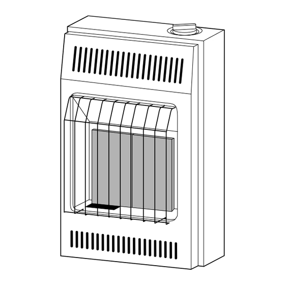
Page 4: Product Identification
FEATURES Front Panel Figure 1 - Vent-Free Propane Gas Heater Install and use heater with care. Follow all local codes. In the absence of local codes, use the latest edition of the National Gas Code ANSI Z223.1, also known as NFPA 54*. -
Page 5: Installing To Wall
INSTALLING TO WALL A qualified service person must install heater. Follow all local codes. CHECK GAS TYPE Use only propane gas. If your gas supply is not propane, do not install heater. Call dealer where you bought heater for proper type heater. INSTALLATION ITEMS Before installing heater, make sure you have the items below: •... - Page 6 For convenience and efficiency, install heater • where there is easy access for operation, inspection, and service • in coldest part of room 8" Minimum From Sides Of Heater Left Side Figure 2 - Mounting Clearances As Viewed From Front of Heater INSTALLING HEATER TO WALL Marking Screw Locations 1.
- Page 7 Installing Two Mounting Screws Note: Wall anchors and mounting screws are in hardware package. The hardware package is provided with heater. Attaching to wall stud method For attaching mounting screw to wall stud 1. Drill hole at marked location using 9/64" drill bit. 2.
- Page 8 Installing Bottom Mounting Screw 1. Locate bottom mounting hole. This hole is near bottom on back panel of heater 2. Mark screw location on wall. 3. Remove heater from wall. 4. If installing bottom mounting screw into hollow or solid wall, install wall anchor. 5.
-
Page 9: Connecting To Gas Supply
CONNECTING TO GAS A qualified service person must connect heater to gas supply. Follow all local codes. SUPPLY Never connect heater directly to the propane supply. This heater requires an external regulator (not supplied). Install the external regulator between the heater and propane supply. The installer must supply an external regulator. -
Page 10: Checking Gas Connections
CHECKING CONNECTIONS IMPORTANT: Hold pressure regulator with wrench when connecting it to gas piping and/or fittings. 3/8" NPT Pipe Nipple Ground Joint Union Manual Shutoff Valve * From External Regulator (11" W.C. to 14" W.C. Pressure) 3" Minimum Figure 11 - Gas Connection * An A.G.A. - Page 11 3. Pressurize supply piping system by either using compressed air or opening propane supply tank valve. 4. Check all joints of gas supply piping system. Apply mixture of liquid soap and water to gas joints. Bubbles forming show a leak. 5.
-
Page 12: Operating Heater
OPERATING HEATER FOR YOUR SAFETY READ BEFORE LIGHTING WARNING ICON If you do not follow these instructions exactly, a fire or explosion may result causing property damage, personal injury or loss of life. A. This appliance has a pilot which must be lighted by hand. When lighting the pilot, follow these instructions exactly. - Page 13 4. Wait five (5) minutes to clear out any gas. Then smell for gas, including near the floor. If you then smell gas, STOP! Follow “B” in the safety information at the top of page 12. If you don’t smell gas, go to the next step. 5.
-
Page 14: To Select Heating Level
TO SELECT HEATING LEVEL WARNING ICON G 001 When running heater, set control knob at LOW or HIGH locked positions. Never set control knob between locked positions. Poor combustion and higher levels of carbon monoxide may result. WARNING ICON Do not try to adjust heating levels by using the manual shutoff valve. -
Page 15: Inspecting Burner
Shutting Off Heater 1. Turn control knob clockwise Shutting Off Burner Only (pilot stays lit) 1. Turn control knob clockwise 1. Remove front panel (see Figure 8, page 8). 2. Follow steps 1 through 6 under LIGHTING INSTRUCTIONS, pages 12 and 13. 3. -
Page 16: Burner Flame Pattern
BURNER FLAME PATTERN Figure 19 shows a correct burner flame pattern. Figure 20 shows an incorrect burner flame pattern. Figure 19 - Correct Burner Flame Pattern Figure 20 - Incorrect Burner Flame Pattern If burner flame pattern is incorrect, as shown in Figure 20 •... -
Page 17: Cleaning And Maintenance
CLEANING MAINTENANCE TROUBLE- SHOOTING Note: All troubleshooting items are listed in order of operation. WARNING ICON Turn off heater and let cool before cleaning. WARNING ICON You must keep control areas, burner, and circulating air passageways of heater clean. Inspect these areas of heater before each use. - Page 18 OBSERVED POSSIBLE PROBLEM CAUSE When control knob is 1. Gas supply turned off or pressed in and turned manual shutoff valve to the PILOT/IGN po- closed sition, there is spark at 2. Control ODS/pilot but no igni- pressed in while being tion turned to PILOT/IGN position...
- Page 19 OBSERVED POSSIBLE PROBLEM CAUSE Burner(s) does not 1. Burner orifice(s) is light after ODS/pilot is clogged 2. Burner orifice(s) di- ameter is too small 3. Inlet gas pressure is too Delayed ignition of 1. Manifold pressure is too burner(s) 2. Burner orifice(s) is clogged Burner backfiring 1.
-
Page 20: Technical Service
TECHNICAL SERVICE WARNING ICON If you smell gas • Shut off gas supply. • Do not try to light any appliance. • Do not touch any electrical switch; do not use any phone in your building. • Immediately call your gas supplier from a neighbor’s phone. -
Page 21: Specifications
SPECIFICATIONS SERVICE HINTS REPLACEMENT PARTS B.T.U. (Variable) Type Gas Ignition Pressure Regulator Setting Inlet Gas Pressure (inches of water) Maximum Minimum Dimensions, Inches (H x W x D) Heater Carton Weight (pounds) Heater Shipping When gas pressure is too low •... -
Page 22: Parts Centrals
PARTS CENTRALS SERVICE PUBLICATIONS ACCESSORY These Parts Centrals are privately owned businesses. They have agreed to support our customer’s needs by providing original replacement parts and accessories. Portable Heater Parts Tarantin Tank Co. 342 N. County Rd. 400 East P.O. Box 6129 Valparaiso, IN 46383 Freehold, NJ 07728 All States... -
Page 23: Parts List
PARTS LIST This list contains replaceable parts used in your heater. When ordering parts, follow the instructions listed under REPLACEMENT PARTS on page 21 of this manual. PART NUMBER DESCRIPTION 098304-01 Screw, #10 x 3/8" 099467-02 Front Panel Assembly 099318-01 Grill Guard 098342-01 Grill Guard Clip... -
Page 24: Warranty Information
WARRANTY INFORMATION Model Serial No. Date Purchased Always specify model and serial numbers when communicating with the factory. We reserve the right to amend these specifications at any time without notice. The only warranty applicable is our standard written warranty. We make no other warranty, expressed or implied. COMFORT GLOW VENT-FREE RESIDENTIAL GAS HEATERS DESA International warrants this product to be free from defects in materials and components for one (1) year from the date of first purchase, provided that the product has been properly installed, operated and maintained in accordance with all...
Need help?
Do you have a question about the Comfort Glow CGP11 and is the answer not in the manual?
Questions and answers